
User manual


3U Servo Amplifier
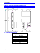
Motor Output Connector
The cable wiring must be shielded and have a separate conductor connecting the motor frame back to the
drive amplifier. The cables are available in cable kits (CABKIT3C) from Delta Tau. (See Appendix A.)
Motor phases are conversed in one of three conventions. Motor manufacturers will call the motor phases
A, B, or C. Other motor manufacturers call them U, V, W. Induction motor manufacturers may call them
L1, L2, and L3. The drive’s inputs are called U, V, and W. Wire U, A, or L1 to the drive’s U terminal.
Wire V, B, or L2 to the drive’s V terminal. Wire W, C, or L3 to the drive’s W terminal.
The motor’s frame drain wire and the motor cable shield must be tied together at the mounting stud (5mm
thread) on the front of the Geo drive product.
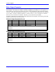
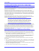
Motor #1 Output Connector Pin-out
Pin # Symbol Function Description Notes
1 U Output Phase1 Axis 1
2 V Output Phase2 Axis 1
3 W Output Phase3 Axis 1
Rake : Connect to motor frame and cable drain, Chassis Ground
CONKIT3C
CABKIT3C
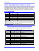
Motor #2 Output Connector Pin-out
Pin # Symbol Function Description Notes
1 U Output Phase1 Axis 1
2 V Output Phase2 Axis 1
3 W Output Phase3 Axis 1
Rake : Connect to motor frame and cable drain, Chassis Ground
CONKIT3C
CABKIT3C
Backplane Board 23