
User manual


3U Servo Amplifier
Wiring 24 V Logic Control
An external 24VDC power supply is required to power the logic portion of the 3U Geo Direct PWM
drive. This power can remain on, regardless of the main AC input power, allowing the signal electronics
to be active while the main motor power control is inactive. The 24V is wired into connector J2 at the
3UBP8A backplane. The polarity of this connection is extremely important. Carefully follow the
instructions in the wiring diagram. This connection can be made using 16 AWG wire directly from a
protected power supply. In situations where the power supply is shared with other devices, it may be
desirable to insert a filter in this connection.
The power supply providing this 24V must be capable of providing an instantaneous current of at least
0.8A to be able to start the DC-to-DC converter in the 3U Geo Direct PWM drive. In the case where
multiple drives are driven from the same 24V supply, it is recommended that each drive be wired back to
the power supply terminals independently. It is also recommended that the power supply be sized to
handle the instantaneous inrush current required to start up the DC-to-DC converter in the Geo drive.
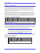
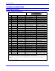
J2: 24VDC Input Logic Supply Connector
Pin # Symbol Function Description Notes
1 +24VDC Input Control power input 24V+/-10% @ 1A
2 RET Common Control power return
Connector is located at the backplane
3UBP8A, 300-603730-10x
Regen (Shunt) Resistor Wiring
The regen circuit is also known as a shunt regulator. Its purpose is to dump power fed back into the drive
from a motor acting as a generator. Excessive energy can be dumped via an external load resistor. The
Geo product series is designed for operation with external shunt resistors of 48 Ω for the 10A, 15A and
20A.These are available directly from Delta Tau as GAR48 and GAR78, respectively. These resistors are
provided with pre-terminated cables that plug into the connector at the backplane.
Caution:
The black wires are for the thermostat and the white wires are for the regen resistor
on the external regen resistor (pictured in Appendix). These resistors can get very
hot. It is recommended that they be mounted away from other devices and near the
top of the cabinet.
The regen resistors incorporate a thermal overload protection device available through the two black leads
exiting the resistor. It is important that these two leads be wired in a safety circuit that stops the system
from operating should the thermostat open.
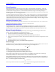
TB2: Regen Resistor Connector
Pin # Symbol Function Description
1 SHUNT RTN Output Regen Resistor output
2 SHUNT Output
Regen Resistor Return
Connector is located at the backplane
3UBP8A, 300-603730-10x
Backplane Board 13