
User manual


3U Servo Amplifier
as FRN-type fuses. Due to the various regulations of local codes, NEC codes, UL and CE requirements,
it is very important to reference these requirements before making a determination of how the input power
is wired.
Additionally, many systems require that the power be able to be turned on and off in the cabinet. It is
typical that the AC power is run through some kind of main control contact within the cabinet, through
the fuses, and then fed to a Geo drive. If multiple Geo drives are used, it is important that each drive has
its own separate fuse block.
Whether single- or three-phase, it is important that the AC input wires be twisted together to eliminate
noise radiation as much as possible. Additionally, some applications may have further agency noise
reduction requirements that require that these lines be fed from an input filtering network.
The AC connections from the fuse block to the Geo drive are made via a cable that is connected at the
backplane with screw terminals.
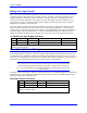
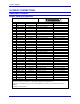
TB1: AC Input Connector Pin-out on the backplane
Pin # Symbol Function Description Notes
1 L1 Input Line Input Phase 1 Not used for single phase input
2 L2 Input Line Input Phase 2
3 L3 Input Line Input Phase 3
3UBP8A, 300-603730-10x
If DC bus is used, use L3 for DC+ and L2 for DC return
Wiring Earth-Ground
Panel wiring requires that a central earth-ground location be installed at one part of the panel. This
electrical ground connection allows for each device within the enclosure to have a separate wire brought
back to the central wire location. Usually, the ground connection is a copper plate directly bonded to the
back panel or a copper strip with multiple screw locations. The Geo drive is brought to the earth-ground
via a wire connected to the stud on the front panel through a heavy gauge, multi-strand conductor to the
central earth-ground location.
Earth Grounding Paths
High-frequency noises from the PWM controlled power stage will find a path back to the drive. It is best
that the path for the high-frequency noises be controlled by careful installation practices. The major
failure in problematic installations is the failure to recognize that wire conductors have impedances at
high frequencies. What reads 0 ohms on a DVM may be hundreds of ohms at 30MHz. Consider the
following during installation planning:
1. Star point all ground connections. Each device wired to earth ground should have its own conductor
brought directly back to the central earth ground plate.
2. Use unpainted back panels. This allows a wide area of contact for all metallic surfaces reducing high
frequency impedances.
3. Conductors made up of many strands of fine conducts outperform solid or conductors with few
strands at high frequencies.
4. Motor cable shields should be bounded to the back panel using 360-degree clamps at the point they
enter or exit the panel.
5. Motor shields are best grounded at both ends of the cable. Again, connectors using 360-degree shield
clamps are superior to connector designs transporting the shield through a single pin. Always use
metal shells.
6. Running motor armature cables with any other cable in a tray or conduit should be avoided. These
cables can radiate high frequency noise and couple into other circuits.
Backplane Board 12