
User manual

3U Servo Amplifier
Amplifier Cooling Considerations
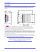
The drive amplifiers produce heat that must be removed. The installation requires that a fan blows air up
through the vertical fins of the product’s heat sink. The 3U Geo Direct PWM drive systems include the
metal plates that go around the unit as part of the rack’s metal panel work and a 24VDC (2.6W) fan. The
fan must be positioned at the bottom side of the drive unit and attached to the fan connector, J3 for
3U042, on the backplane for power.
Caution:
Do not operate the amplifier without an operational fan.
Do not impede airflow through the unit.
Single Phase Operation
Due to the nature of power transfer physics, it is not recommended that any system design attempt to
consume more than 2kW from any single-phase mains supply. Even this level requires careful
considerations. The simple bridge rectifier front end of the Geo Drive, as with all other drives of this
type, require high peak currents. Attempting to transfer power from a single-phase system getting one
charging pulse each 8.3 milliseconds causes excessively high peak currents that can be limited by power
mains impedances. The 3U Geo Direct PWM Drive output voltage sags, the input rectifiers are stressed,
and these current pulses cause power quality problems in other equipment connected to the same line.
While it is possible to operate drives on single-phase power, the actual power delivered to the motor must
be considered. Never design expecting more than 1.5 HP total from any 115V single-phase system and
never more than 2.5 HP from any 230V single-phase system.
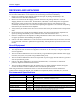
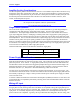
Check the table below on how to calculate how to derate at single phase.
110VAC single phase 230VAC single phase
3U042 10% Not needed
Note: Output Wattage derrates @ single phase.
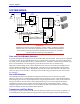
Power Supply Considerations
The 3U Geo Direct PWM Amplifiers require an external mains connection to the barrier block on the
back side of the backplane to create the motor bus power. This connection can be single phase or three-
phase AC power at 115 or 230Vac. A single-phase system cannot provide more than 1500-2000 watts.
The form factor of the current becomes exaggerated perhaps allowing the internal rectifier bridge to be
damaged and electrical noise to interfere with other electronic equipment. These connections must be
fused with slow blow (i.e., FRN) fuses. Recommended fusing is 20A for the 3U042.
The logic power for the amplifier is derived from a separate external 24VDC @1A power supply. The
3U Drives have internal DC-to-DC converters that isolate the drive from this power supply and create all
the internally required logic voltages. Startup current from this power external power supply is isolated
with a soft start circuit
A Protective Earth Ground must be connected to the backplane (3UBP8A) and to the 3U rack itself. The
ground should be a low impedance path directly returning to the main earth distribution block within the
machine enclosure.
Wiring AC Input
The main bus voltage supply is brought to the Geo drive through connector TB1 on the backplane board.
If single phase is used, derrating needs to be calculated. It is acceptable to bring the single-phase power
into any two of the three input pins on connector TB1. Higher-power drive amplifiers require three-phase
input power. It is extremely important to provide fuse protection or overload protection to the input
power to the Geo drive amplifier. Typically, this is provided with fuses designed to be slow acting, such
Backplane Board 11