
User manual

3U Servo Amplifier
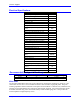
Electrical Specifications
Output Circuits (axes)
2
Nominal Input Voltage (VAC)
230
Rated Input Voltage (VAC)
97-265
Rated Continuous Input Current (A AC
RMS
)
5.28
Rated Input Power (Watts)
2103
Frequency (Hz)
50/60
Phase Requirements
1Φ or 3Φ
Charge Peak Inrush Current (A)
Main Bus Capacitance (µf), backplane
board
940
Rated Output Voltage (V)
138
Rated Cont. Output Current per Axis
4
Peak Output Current (A) for 2 seconds
8
Rated Output Power per Axis (Watts)
956
Nominal DC Bus
325
Over-voltage Trip Level (VDC)
410
Under-voltage Lockout Level (VDC)
10
Turn-On Voltage (VDC)
392
Turn-Off Voltage (VDC)
372
Maximum Current (A)
Recommended Current (A)
Minimum Resistance (Ohms)
Maximum Power (W)
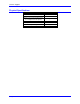
Recommended Load Resistor (300 W
Max.)
GAR48
Input Voltage (VDC)
20-27
Input Current (A)
1
Inrush Current (A)
2
Resolution (bits)
12
Full-scale Signed Reading (±A)
13.01
Maximum PWM Frequency (kHz) @ rated
current
12
Minimum Dead Time (µs)
1
Charge Pump Time (% of PWM period.)
5
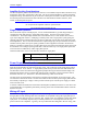
Recommended Fusing and Wire Gauge
Model Recommended Fuse (FRN/LPN) Recommended Wire Gauge*
3U042 20 12 AWG
* See local and national code requirements
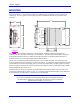
Wire Sizes
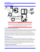
3U Geo Direct PWM Drive electronics create a DC bus by rectifying the incoming AC electricity. The
current flow into the drive is not sinusoidal but rather a series of narrow, high-peak pulses. Keep the
incoming impedance small so that these current pulses are not hindered. Conductor size, transformer size,
and fuse size recommendations may seem larger than normally expected. All ground conductors should
be 8AWG minimum using wires constructed of many strands of small gauge wire. This provides the
lowest impedance to high-frequency noises.
Backplane Board 6