
User manual

3U Servo Amplifier
can drive any range of back EMF motor, but the back EMF is highly related to the other parameters of the
motor such as the motor inductance and the motor Kt. It is the back EMF of the motor that limits the
maximum achievable speed and the maximum horsepower capability of the motor.
Motor Torque Constant
Motor torque constant is referred to as Kt and usually it is specified in torque-per-amp. It is this number
that is most important for motor sizing. When the load that the motor will see and the motor’s torque
constant is known, the drive amplifier requirements can be calculated to effectively size a drive amplifier
for a given motor. Some motor designs allow Kt to be non-linear, in which Kt will actually produce less
torque per unit of current at higher output speeds. It is wise to de-rate the systems torque producing
capability by 20% to allow headroom for servo control.
Motor Inertia
Motor inertial comes into play with motor sizing because torque to accelerate the inertia of the motor is
effectively wasted energy. Low inertia motors allow for quicker acceleration. However, consider the
reflective inertia from the load back to the motor shaft when choosing the motor’s inertial. A high ratio of
load-to-motor inertia can cause limited gains in an application if there is compliance in the transmission
system such as belt-drive systems or rubber-based couplings to the systems. The closer the rotor inertia
matches the load’s reflected inertia to the motor shaft, the higher the achievable gains will be for a given
system. In general, the higher the motor inertia, the more stable the system will be inherently.
Mechanical gearing is often placed between the load and the motor simply to reduce the reflected inertia
back to the motor shaft.
Motor Cabling
Motor cables are an integral part of a motor drive system. Several factors should be considered when
selecting motor cables. First, the PWM frequency of the drive emits electrical noise. Motor cables must
have a good-quality shield around them. The motor frame must also have a separate conductor to bring
back to the drive amplifier to help quench current flows from the motor due to the PWM switching noise.
Both motor drain wire and the cable shield should be tied at both ends to the motor and to the drive
amplifier.
Another consideration in selecting motor cables is the conductor-to-conductor capacitance rating of the
cable. Small capacitance is desirable. Longer runs of motor cable can add motor capacitance loading to
the drive amplifier causing undesired spikes of current. It can also cause couplings of the PWM noise
into the earth grounds, causing excessive noise as well. Typical motor cable ratings would be 50 pf per
foot maximum cable capacitance.
Another factor in picking motor cables is the actual conductor cross-sectional area. This refers to the
conductor’s ability to carry the required current to and from the motor. When calculating the required
cable dimensions, consider agency requirements, safety requirements, maximum temperature that the
cable will be exposed to, the continuous current flow through the motor, and the peak current flow
through the motor. Typically, it is not suggested that any motor cable be less than 14 AWG.
The motor cable’s length must be considered as part of the application. Motor cable length affects the
system in two ways. First, additional length results in additional capacitive loading to the drive. The
drive’s capacitive loading should be kept to no more than 1000 pf. Additionally, the length sets up
standing waves in the cable, which can cause excessive voltage at the motor terminals. Typical motor
cable length runs of 200 feet for 230V systems and 50 feet for 480V systems are acceptable. Exceeding
these lengths may put other system requirements in place for either a snubber at the motor end or a series
inductor at the drive end. The series inductor at the drive end provides capacitance loading isolation from
the drive and slows the rise time of the PWM signal into the cable, resulting in less voltage overshoot at
the motor.
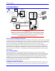
Backplane Board 4