
User manual


3U Servo Amplifier
Motor over temperature (input from motor) •
•
•
•
•
•
•
•
Under voltage
IGBT thermal failure
PWM fault
Over voltage
Ground fault
Minimum dead time protection
Shoot through protection
Note:
The 3U drive products are available in kit-form. The electronics on these products are
subject to damage by static electricity. Handle it as little as possible. Use ground wrist
straps when handling. Do not allow static-charge holding materials (paper, plastic, etc.)
to come in near proximity of the product.
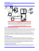
Typically, the position feedback is fed to the PMAC controller via the available accessories and is not part
of the 3U drive amplifier. Thus, the position feedback is not to be connected to the amplifier in any
way.
Compatible Motors
The 3U Geo Direct PWM product line is capable of interfacing to a wide variety of motors. The 3U Geo
Direct PWM drives can be used with almost any type of three-phase brushless motor, including DC
brushless rotary, AC brushless rotary, induction, and brushless linear motors. Motor selection for an
application is a science in itself and cannot be covered in this manual. However, some basic
considerations and guidelines are offered. Motor manufacturers include a host of parameters to describe
their motor.
Some basic equations can help guide an applications engineer to mate a proper drive with a motor. A
typical application accelerates a load to a speed, running the speed for a while and then decelerating the
load back into position.
Maximum Speed
The motor’s maximum rated speed is given. This speed may or may not be achievable in a given system.
The speed could be achieved if enough voltage and enough current loop gain are available. Also,
consider the motor’s feedback adding limitations to achievable speeds. The load attached to the motor
also limits the maximum achievable speed. In addition, some manufacturers will provide motor data with
their drive controller, which is tweaked to extend the operation range that other controllers may be able to
provide. In general, the maximum speed can be determined by input voltage line-to-line divided by Kb
(the motor’s back EMF constant). It is wise to de-rate this a little for proper servo applications.
Torque
The torque required for the application can be viewed as both instantaneous and average. Typically, the
instantaneous or peak torque is calculated as a sum of machining forces or frictional forces plus the forces
required to accelerate the load inertia. The machining or frictional forces on a machine must be
determined by the actual application. The energy required to accelerate the inertia follows the equation: t
= JA, where t is the torque in pound-feet required for the acceleration, J is the inertia in pound-feet-
second squared, and A is in radians per second per second. The required torque can be calculated if the
desired acceleration rate and the load inertia reflected back to the motor are known. The t-JA equation
requires that the motor’s inertia be considered as part of the inertia-requiring torque to accelerate.
Once the torque is determined, the motor’s specification sheet can be reviewed for its torque constant
parameter (Kt). The torque required at the application divided by the Kt of the motor provides the peak
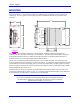
Backplane Board 2