
Installation manual

Geo Direct PWM Amplifier
Specifications 8
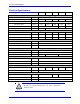
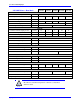
Electrical Specifications
230 VAC Drives – Single Axis
GxL051
GxL101
GxL151
GxL201
GxL301
Main Input Power
Main AC Input
[VAC rms]
110
-20%
– 240
+10%
(~87 – 264)
Rated Input Current @ 240VAC 3
[A rms]
3.3
6.6
9.9
13.2
19.8
Frequency
[Hz]
50/60 Hz
Rated Input Power
[Watts]
1315
2629
3944
5259
7888
Main Bus Capacitance
[µf]
3380
5020
6800
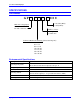
AC Input Phase Requirement
1Φ or 3Φ
3Φ
Output
Continuous Current Output per Axis
[A rms]
5
10
15
20
30
Peak Current Output per Axis @ 2 sec
[A rms]
10
20
30
40
60
Power Output per Axis
[Watts]
1195
2390
3585
4780
7171
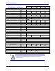
Bus Protection
Nominal DC Bus
[VDC]
325
Over-Voltage Trip Level
[VDC]
410
Under-Voltage Lockout Level
[VDC]
137
Shunt Resistor
Shunt Turn-On Voltage
[VDC]
392
Shunt Turn-Off Voltage
[VDC]
372
Shunt Resistor (300 W max)
GAR78
GAR48
GAR48-3
Logic Power
Input Voltage
[VDC]
20 – 27
Input Current
[A rms]
2
Inrush Current
[A]
4
Current Feedback
Full Scale Reading
[A]
16.26
32.53
48.79
65.05
97.58
Resolution
[bits]
12
Transistor Control
Recommended PWM Frequency
[KHz]
12
10
8
Minimum Dead time
[µs]
1
Charge Pump Time (% of PWM Period)
5
Note
All values are at ambient temperature of 0 – 45°C (113 F) unless
otherwise stated.