
Installation manual

Geo Direct PWM Amplifier
Connector PinOuts and Wiring 26
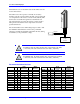
Note
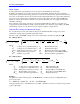
Ferrite cores are also commonly used with lower inductance motors to
enhance compatibility with the Geo Direct PWM Drive, which is
specified to a minimum of 2 mH.
Do not use a motor wire gauge less than 14 AWG for 5/10A or 8/16A axes, and 10 AWG for
15/30A or 30/60A axes unless otherwise specified by the motor manufacturer. Refer to Motor
manufacturer and local code recommendations.
Avoid running sensitive signal cables (i.e. encoders, small signal transducers) in the same cable
bundle as the motor cable(s).
Install dv/dt filter, Trans-coil V1K series (Optional).
Motor Selection
The Geo Direct PWM Drive interfaces with a wide variety of motors. It supports virtually any kind of
three-phase AC/DC rotary, linear brushless, or induction motors. Using two out of the three phases, it is
also possible to drive permanent magnet DC brush motors.
Motor Inductance
Digital direct PWM control requires a significant amount of motor inductance to drive the on-off voltage
signals resulting smooth current flow with minimal ripple. Typically, servomotors’ phase inductance
ranges from 2 to 15mH. The lower the inductance, the higher is the suitable PWM frequency.
Low inductance motors (less than 2 mH) can see large ripple currents causing excessive energy waste and
overheating. Additional in-series inductance is recommended in these cases.
High inductance motors (greater than 15 mH) are slower to react and generally not considered high
performance servo motors.
Motor Resistance
Motor resistance is not typically a determining factor in the drive/system performance but rather comes
into play when extracting a desired torque or horsepower out of the motor is a requirement.
Motor Inertia
Motor inertia is an important parameter in motor sizing. Considering the reflected load inertia back to the
motor in this process is important. In general, the higher the motor inertia, the more stable the system will
inherently be. A high ratio of load to motor inertia shrinks the operating bandwidth (gain limited) of the
system, especially in applications using belt or rubber based couplings. The ratio of load to motor inertia
is typically around 3:1. Mechanical gearing is often used to reduce reflected inertial load going back to
the shaft of the motor.
Motor Speed
In some applications, it is realistically impossible to achieve the motors’ specified maximum velocity.
Fundamentally, providing sufficient voltage and proper current-loop tuning should allow attaining motor
maximum speeds. Consider feedback devices being a limitation in some cases, as well as the load
attached to the motor. In general, the maximum speed can be determined dividing the line-to-line input
voltage by the back EMF constant Kb of the motor. Input voltage headroom of about 20% is
recommended for good servo control at maximum speed.