
Installation manual

Geo Direct PWM Amplifier
Connector PinOuts and Wiring 24
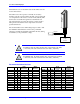
J2 – J3: Motor Wiring
The cable wiring must be shielded and have a separate conductor connecting the motor frame back to the
Geo Direct PWM Drive’s chassis.
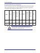
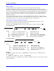
J2 – J3: Molex 3-Pin Female
Mating: Molex 3-Pin Male
W
V
U
Tie ground and shield
to chassis stud
Symbol
Function
Description
U
Motor Output
Axis 1 Phase 1
V
Motor Output
Axis 1 Phase 2
W
Motor Output
Axis 1 Phase 3
DT Housing pn: 014-H00F03-049
DT Pins pn: 014-042815-0031
Molex housing pn: 42816-0312
Molex pins pn: 42815-0031
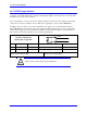
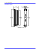
GPx201, GPx301
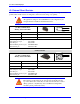
J2 – J3: Molex 4-pin Female
Mating: Molex 4-pin Male
GND
W
V
U
Symbol
Function
Description
U
Motor Output
Axis 1 Phase 1
V
Motor Output
Axis 1 Phase 2
W
Motor Output
Axis 1 Phase 3
GND
Ground
DT Housing pn: 014-H00F04-049
DT Pins pn: 014-042815-0031
Molex housing pn: 42816-0412
Molex pins pn: 42815-0031
Note
The Geo Direct PWM Drive endorses the U, V, and W nomenclature
for phases 1 through 3 respectively. Some motor manufacturers will
call them A, B, and C. Others may call them L1, L2, and L3.
Note
For wiring DC brush motors, use phases U and W, and leave V
floating.