
Installation manual

Geo Direct PWM Amplifier
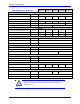
Connector PinOuts and Wiring 19
Note
AC input wires must be twisted together to eliminate as much noise
radiation as possible.
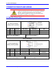
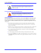
Recommended Main Bus Power Wiring/Protection
Caution
Main bus power lines should run in a separate duct (at least 12” or 30
cm away) from and should never be bundled with the I/O signal,
communication, or encoder cables.
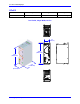
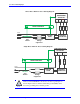
Grounding, Bonding
System grounding is crucial for proper performance of the Geo Direct PWM Drive. Panel wiring requires
that a central earth-ground (also known as ground bus bar) location be installed at one part of the panel.
The ground bus bar is usually a copper plate directly bonded to the back panel. This electrical ground
connection allows for each device within the enclosure to have a separate wire brought back to the central
earth-ground.
Motor shields are best grounded at both ends of the cable. Motor cable shields should be
bonded to the back panel using 360-degree clamps at the point they enter or exit the panel.
Always use metal shells.
Implement a star point ground connection scheme; so that each device wired to earth ground
has its own conductor brought directly back to the central earth ground plate (bus bar).
Use an unpainted back panel. This allows a wide area of contact for all metallic surfaces,
reducing frequency impedances.
Use a heavy gauge ground earth conductors made up of many strands of fine conducts.
The Geo Direct PWM Drive is brought to the earth-ground via one or two wire(s) connected
to the M4 mounting stud(s) through a heavy gauge multi-strand conductor to the central
earth-ground.