
Installation manual

Geo Direct PWM Amplifier
Mounting, Physical Layout 13
MOUNTING, PHYSICAL LAYOUT
The location of the Geo Direct PWM Drive is important. Installation should be in an area that is
protected from direct sunlight, corrosives, harmful gases or liquids, dust, metallic particles, and other
contaminants. Exposure to these can reduce the operating life and degrade performance of the drive.
Several other factors should be carefully evaluated when selecting a location for installation:
For effective cooling and maintenance, the Geo Direct PWM Drive should be mounted on a
smooth, non- flammable vertical surface.
At least 76 mm (3 inches) top and bottom clearance must be provided for air flow. At least 10
mm (0.4 inches) clearance is required between units (each side).
Temperature, humidity and Vibration specifications should also be taken in account.
Caution
Unit must be installed in an enclosure that meets the environmental IP
rating of the end product (ventilation or cooling may be necessary to
prevent enclosure ambient from exceeding 45° C [113° F]).
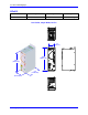
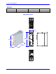
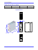
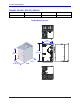
The Geo Direct PWM Drive can be mounted with a traditional 4-hole panel mount, two U shape/notches
on the bottom and two pear shaped holes on top.
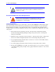
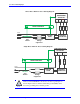
If multiple Geo Direct PWM Drives are used, they can be mounted side-by-side, leaving at least a 122
mm clearance between drives. This means a 122 mm center-to-center distance (0.4 inches) with the 4-
axis Drives. 8- and 6-axis Geo Direct PWM Drives can be mounted side by side at 214 mm center-to-
center distance (8.4 inches). It is extremely important that the airflow is not obstructed by the placement
of conduit tracks or other devices in the enclosure.
If the drive is mounted to a back panel, the back panel should be unpainted and electrically conductive to
allow for reduced electrical noise interference. The back panel should be machined to accept the
mounting bolt pattern of the drive.
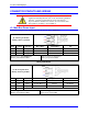
The Geo Direct PWM Drive can be mounted to the back panel using four M4 screws and internal-tooth
lock washers. It is important that the teeth break through any anodization on the drive’s mounting gears
to provide a good electrically conductive path in as many places as possible. Mount the drive on the back
panel so there is airflow at both the top and bottom areas of the drive (at least three inches).