
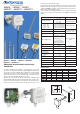
Data Sheet

65
18.8
56.3
Ø 6,5
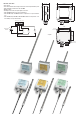
Installation notes
• The window of the sensor (or of the sensors) must be oriented in the direction
of flow. To facilitate the proper positioning of the probe, eg. inside of a pipe, a
graduated scale, engraved along the stem, indicates the depth of introduction
of the window speed sensor in the channel. To properly orient the sensor to the
flow, once introduced into the channel, the air speed window and line on the
base of the scale are on the same axis.
5
50mm
678910
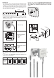
• To fix the probe inside a ventilation duct, a pipe , etc. you can use, for example,
HD9008.31.12 flange, a PG16.12 metal cable gland (Ø10…14mm) or a 3/8”
universal biconical connection.
HD9008.31.12 Flange
D
H L
A
PG16.12 metal cable gland
D = 10…14mm
L = 6.5mm
H = 23mm
A = PG16
L
D
D
Universal biconical connector
L = 35mm
D = 14mm
A = 3/8”
• The transmitters are factory calibrated and no further adjustments are re-
quired.
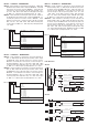
• To select the air speed output range by using the dual dip-switch on the
board, please see the chart below:
Output range 0…1m/s 0…2m/s 0…10m/s 0…20m/s
Dip-switch
position
• Dip-switch should always be at the end of its final limit in both directions.
• The jumper on the board selects an integrated response time in 0.2s in the
FAST position and in 2s in the SLOW position. Please set the integration
time at SLOW in case of turbulence, otherwise please select the FAST
position.
HD9008.31.12 Flange