
User's Manual
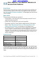
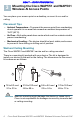
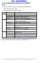
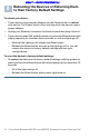
Table Of Contents
- Before You Begin
- Cisco WAP551 and WAP561 Wireless-N Access Point Features
- Mounting the Cisco WAP551 and WAP561 Wireless-N Access Points
- Connecting the Cisco WAP551 and WAP561 Wireless-N Access Points
- Verifying the Hardware Installation
- Getting Started with the Configuration
- Suggested Next Steps
- Rebooting the Devices or Returning them to their Factory Default Settings
- Where to Go From Here

Cisco Small Business WAP551 and WAP561 Wireless-N Access Point with PoE 3
DRAFT -- CISCO CONFIDENTIAL
Cisco WAP551 and WAP561 Wireless-N
Access Point Features
Front Panel
The front panel of the devices consists of three lights: Power, WLAN, and
LAN. For full descriptions of the colors of the lights and their indications,
see “Verifying the Hardware Installation”. A Kensington lock slot is found
under the lights.
Back Panel
The back panel of the devices consists of:
• Power Button—Use this button to turn the power on and off. It is not
applicable when using PoE.
• Power Jack—Use this jack if you are not using PoE.
• Kensington Lock Slot—Use to attach a cable and lock to the device.
• Reset—See “Rebooting the Devices or Returning them to their
Factory Default Settings” for information on the Reset button.
• RJ-45 Ethernet Port—Use this auto-sensing, Gigabit Ethernet (802.3)
port to connect to network devices, such as computers, routers, or
switches. Cisco strongly recommends using Cat5 or better cable for
Gigabit connectivity. You may use the Ethernet port to power your
device using PoE.
Default Settings
If you are using a Cisco Small Business RV Series router, the default range
for the DHCP assigned address is from 192.168.1.100 to 192.168.1.254. Any
device connecting to the same LAN will be assigned an IP address in this
range.
Parameter Default Value
Username cisco
Password cisco
LAN IP Address DHCP address assigned
by server
Fallback LAN IP 192.168.1.245
Subnetwork Mask 255.255.255.0
2