
User's Manual
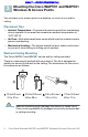
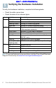
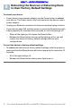
Table Of Contents
- Before You Begin
- Cisco WAP551 and WAP561 Wireless-N Access Point Features
- Mounting the Cisco WAP551 and WAP561 Wireless-N Access Points
- Connecting the Cisco WAP551 and WAP561 Wireless-N Access Points
- Verifying the Hardware Installation
- Getting Started with the Configuration
- Suggested Next Steps
- Rebooting the Devices or Returning them to their Factory Default Settings
- Where to Go From Here

Cisco Small Business WAP551 and WAP561 Wireless-N Access Point with PoE 5
DRAFT -- CISCO CONFIDENTIAL
To mount the WAP device to a wall or ceiling:
STEP 1 Determine where you want to mount the device. Verify that the
surface is smooth, flat, dry, and sturdy.
STEP 2 Drill two pilot holes into the surface x.xx inches (xx mm) apart for
your Cisco WAP device.
STEP 3 Insert a screw into each hole, leaving a gap between the surface
and the base of the screw head.
STEP 4 Place the upper slots of the bracket over the screws, adjust the
screws accordingly, and slide the bracket down until the screws fit
snugly into the slots.
STEP 5 Using the bracket as a template, drill two more holes for the lower
screws.
STEP 6 Insert a screw into each lower hole.
STEP 7 Slide the WAP device into the bracket, placing the cables or cords
through the break-out tab found in the back of the bracket.
Connecting the Cisco WAP551 and
WAP561 Wireless-N Access Points
These instructions assume that your will be using PoE to power your WAP
device. If PoE is not provided, power adaptors are sold separately; see
Where to Go From Here, page 11. To connect the device to the network:
STEP 1 Connect the Ethernet cable to the Ethernet port of a switch or a
router.
STEP 2 Connect the other end of the network Ethernet cable to the
Ethernet port of the wireless access point.
After installation, all lights should be active. Refer to Verifying the
Hardware Installation, page 6 for details about the different lights on each
switch.
4