
Installation manual

10. Settings
Operation and Installation Manual for SOLIVIA 2.0/2.5/3.0/3.3/3.6/5.0 EU G4 TR
58
10.10 Reactive Power Control
NOTE
Reactive power control is only available for DE
LVD and DK LVD grids.
NOTE
Changes to active and reactive power control
can affect energy production.
Ask your installer before changing the settings.
10.10.1 Overview
Function/Mode Description
Power factor by active
power
For setting a value of cos φ (inductive or
capacitive) depending on the active power
ratio P/P
n
Constant power factor For setting a xed value for cos φ (induc-
tive or capacitive)
Only one mode can be active at one time.
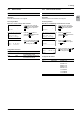
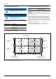
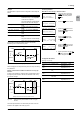
10.10.2 PowerFactorbyActivePowercosφ(P)
Menu 520 Reactive PwCtrl
Description
This function can be used to determine a separate cos φ for four
different power ratios P/P
n
(see “Fig. 10.3 Setting Ranges for “cos φ
(P)” Function”, p. 58).
P/P
n
is the ratio between the current active power and the rated
power of the solar inverter. Power ratio and cos φ are assigned
to points in pairs. The power ratios for points A and D are xed at
0%/100%. For points B and C, the power ratios can be congured
within the predened limits. The cos φ can be congured for all four
points.
For example, the parameters B P/Pn ratio and B cos phi
belong to point B. The parameters A P/Pn ratio and D P/Pn
ratio are not displayed, since they are xed at 0 %/100 %.
Power ratio point D = 100 %
(cannot be changed)
Power ratio point A = 0 %
(cannot be changed)
Power ratio P/P
n
0 % 50 % 100 %
Inductive cos φ
point C (0.8 ... 1)
1
0.8
0.8
1
0.8
0.8
Power ratio point C
(50 ... 99 %)
Power ratio point B
(1 ... 49 %)
Capacitive cos φ
point D
(0.8 ... 1)
Inductive cos φ
point D
(0.8 ... 1)
Capacitive cos φ
point A
(0.8 ... 1)
Inductive cos φ
point A
(0.8 ... 1)
Capacitive cos φ
point C (0.8 ... 1)
Inductive cos φ
point B (0.8 ... 1)
Capacitive cos φ
point B (0.8 ... 1)
cos φ
cos φ
Fig. 10.3: Setting Ranges for "cos φ (P)" Function