
Installation manual

7. Installation
Operation and Installation Manual for SOLIVIA 2.0/2.5/3.0/3.3/3.6/5.0 EU G4 TR
32
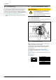
7.4.4 Grounding DC Side
The solar inverter can be grounded at either the DC+ side or the
DC- side. The ground connection must be installed near the solar
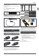
inverter. We recommend using the grounding kit from Delta.
The DC side of the solar inverter has an insulation and grounding
monitor. Monitoring can be congured in the 230 Grounding menu,
see “10.13 Insulation and grounding monitoring”, p. 61.
► Install the ground kit according to the manual delivered with
the kit.
7.5 Connecting RS485 (EIA485) - Optional
ATTENTION
To ensure IP65 protection, all unused connec-
tions and interfaces must be closed using the
covers on the solar inverter.
Only the cables described below may be used.
Standard cables are not permitted.
7.5.1 General Instructions
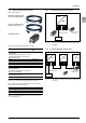
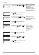
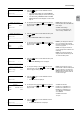
One or more solar inverters can be connected to a monitoring sys-
tem using the RS485 interfaces (see Fig. 7.9, p. 32).
Fig. 7.9: Location of RS485 connection
The two RS485 interfaces are internally wired 1:1. Each RS485
interface can be used as an input or output.
If multiple solar inverters are connected to a monitoring system
using the RS485, a separate RS485 ID must be congured for
each solar inverter.
The RS485 ID can be set during commissioning (see Fig. 7.1,
p. 24) or later during operation (see “10.6 RS485 (EIA485) Set-
tings”, p. 54).
A termination resistor must be connected to the last solar inverter,
see Fig. 7.11, p. 33.
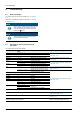
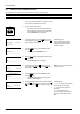
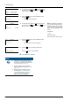
Pin Assignments
Pin Assignment
8 1
1 Reserved
2 Reserved
3 Reserved
4 GND
5 Reserved
6 Reserved
7 TX_A
8 RX_B