
Installation manual


40
WiringtheInverter
To remove the communication module follow these instructions:
1. Unscrew and remove the two Phillips screws highlighted in red in Figure 5.10.
2. Remove the front plate as shown.
3. Carefully pull out the communication module from the inverter. Remove glands and plugs
where applicable.
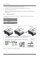
5.5.1 RS485Connection
The pin de nition of RS485 is shown in Table 5.2. The wiring of multi-inverter connections is
shown in Figure 5.11.
PIN FUNCTION
4 GND
7 DATA+
8 DATA-
Table 5.2.: De nition of RS485 pin
4 GND
7 DATA+
8 DATA-
Inverter #1* Inverter #2 Inverter #N
EveryinvertermusthaveadifferentIDsettinginthesamechain.
Terminal Resistor:
120Ω (0.5W)
Data + to Data -
*Activate the Terminal Resistor by setting
the internal dip switch no. 2 to on. See Figure 5-12 for this procedure.
Figure 5.11.: Multi-inverter Connection Illustration