
Installation manual


33
ENGLISH
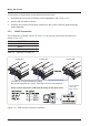
WiringtheInverter
Inverter
Next tighten the cable gland (2) to the connector hous-
ing (1). Tightening torque for cable sheath diameters
between 11 and 20 mm: 6 to 8 Nm. Rotate the coupling
ring (3) to mate the connector with the inverter‘s AC plug.
After wiring the mating connector, screw
the connector housing (1) to the coupling
ring (3). To do this push the coupling
ring (3) to the connector housing (1) and
tighten 1-2 Nm.
Rotate the connector housing and cable
gland to remove them from the coupling
ring.
The female cable
connector needs to
be wired as shown
below.
To wire the connector refer to placement
of L1, L2, L3, N and PE shown to the left.
Screw termination is provided to x the
wires to the contacts.
(1) (2)
(3)
NOTE:Rearviewofcable
connector
L3
L1
L2
PE
1 : L1
2 : L2
3 : L3
4 : N
: PE
N
L1
L2
L3
N
PE
Cable
Slide the connector housing and cable
gland onto the cable.