
Installation manual


28
WiringtheInverter
5. WiringtheInverter
5.1 PreparationbeforeWiring
1. To avoid accidents, please conrm that the PV inverter’s power of both DC and AC are
switched off.
2. Please conrm whether the input/output of PV inverter’s wiring are clearly indicated. Make
sure that the value, polarity, voltage and phase are correct.
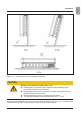
3. The wiring procedure of a PV system is shown in gure 5-1 and 5-2. Wiring details are de-
scribed in the following paragraphs.
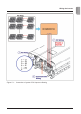
– When the DC input is oating, an external transformer is not necessary. Please refer
to Figure 5-1 for the connection. The inverter can accept DC inputs in parallel (1 MPP
tracker) or separate DC input connections (2 MPP Tracker).
– Operating in parallel DC inputs (1 MPP Tracker)
Inverter MPPT: Power sharing decided by each input’s impedance
Boost MPPT: >10 kW, inverter will force to balance the DC1 & DC2 power
<10 kW, inverter will not force to balance the DC1 & DC2
power
– Operating in separated DC inputs (2 MPP Trackers)
The max. rating is 10.5kW/30A for each input.
CAUTION
Machineandequipmentdamagemayoccur.
► When the DC input is a positive ground or negative ground, all of the
strings must be connected in parallel and then connected to the invert-
ers. In addition, an external isolation transformer must be installed on
the AC side, otherwise, damage will result and the inverter will not work
properly. Different DC input wiring needs require different insulation
detection settings. To learn more about the settings, please refer to
„6.3.6.2 Install Settings“ on page 54.