
User manual

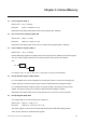
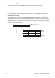


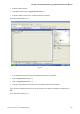


Table Of Contents
- Cover
- Preface
- Table of Contents
- Chapter 1 Introduction
- Chapter 2 Creating and Editing Screens
- 2.1 ScrEdit (Screen Editor) Setup
- 2.2 How to Start ScrEdit
- 2.3 Menu Bar and Toolbar (File)
- 2.4 Menu Bar and Toolbar (Edit)
- 2.5 Menu Bar and Toolbar (View)
- 2.6 Menu Bar and Toolbar (Element)
- 2.7 Menu Bar and Toolbar (Screen)
- 2.8 Menu Bar and Toolbar (Tools)
- 2.9 Menu Bar and Toolbar (Options)
- 2.10 Menu Bar and Toolbar (Window)
- 2.11 Menu Bar and Toolbar (Help)
- Chapter 3 Element Function
- Chapter 4 Macro Function
- Chapter 5 Control Block and Status Block
- Chapter 6 Internal Memory
- Chapter 7 Example Explanation
- Appendix A Specifications and Installation
- Appendix B USB Flash Drive Function
- Appendix C Main Menu Operation of HMI System
Chapter 7 Example Explanation|ScrEdit Software User Manual
Revision Apr. 30th, 2007, 2007PDD23000002 7-5
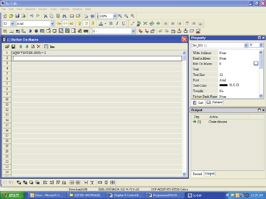
• Select the Edit On Macro
• In the Macro section type in (2@INVERTER-2000) = 2
• This will cause the Drive to turn on when the button is selected.
The screen will look like Fig. 7.6.
Fig. 7.6
• Go to the Screen drop down and at the bottom select Screen Cycle Macro
• Type in (2@INVERTER-0200) = 3
• Type in (2@INVERTER-0201) = 4
• This set’s up the drive to accept control from the HMI via RS485 communication.
In the Screen Cycle Macro the user must set-up the Drive to accept the commands coming from the
HMI.
The screen will look like Fig. 7.7.