
Product data

DeltaV Product Data Sheet
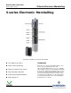
October 2014 – Page 3 S-Series Electronic Marshalling
Product Description
Electronic Marshalling hardware includes:
CHARM I/O Carrier (DIN rail mounted and supports
redundant pair of CHARM I/O Cards, redundant 24
VDC power connectivity, and redundant Ethernet
communication modules)
CHARM I/O Card (provides communication between
CHARMs and the Ethernet I/O network to S-series
controllers)
CHARM Base plate (DIN rail mounted with
interleaving power and bus connectors. Supports 12
CHARMs and their terminal blocks, as well as
connection for injected field power)
CHARM Terminal Block (removable terminal block
providing terminal connections to field wiring and
physical latch for CHARM)
CHARMs (Characterization Module for each field
signal. Provides basic analog to digital conversion
and signal isolation to the redundant communication
bus)
Cable Extenders that provide flexibility in carrier
mounting.
I/O bus termination (provides bus terminations for
redundant I/O bus)
Labeling features for baseplate and channel
identification.
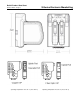
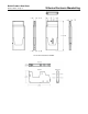
CHARM I/O Card (CIOC) with CHARMs
The CHARM I/O card carrier is mounted to the top of a
vertical DIN rail and up to eight CHARM Baseplates are
mounted below it, snapping easily to the DIN rail as they
are connected to each other. The bus termination
assembly is attached at the bottom. A standard DIN-rail
lock is used to keep the entire assembly in place.
A pair of CHARM I/O Cards installs on the carrier and
communicates over a redundant Ethernet network with up
to 4 controllers, allowing great flexibility and ease of
system expansion. Communication modules are available
for copper and fiber optic media.
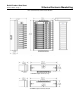
Each baseplate is ordered with 12 terminal blocks:
standard terminal blocks or fused injected power terminal
blocks. Electronic Marshalling eliminates the need to
partition the I/O wiring to specific channels based on
signal type. Simply connect field signal multi-cores in an
orderly fashion as desired. Install the appropriate CHARM
to complete the field circuit and the signal is ready to be
used by any one of 4 S-series controllers. No cross-wiring
required.
Each CHARM acts as a circuit protection device and field
wiring disconnect. Signals are inherently current limited to
protect against wiring faults to ground. Each CHARM
provides surge protection to meet industry standards in
the area of EMC. Under extreme overvoltage conditions
due to incorrect field wiring, the CHARM will act as a fuse
to protect adjacent channels. Signal faults are thus
isolated to the single CHARM.
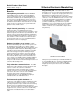
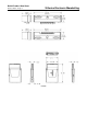
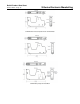
CHARMs can be partially
ejected to a locked
position that disconnects
the field wiring from the
system to perform field
maintenance actions or to
remove power to a field
device. Activating the
CHARM latch ejects the
CHARM to the detent
position. Closing the latch
locks the CHARM in place
and isolates the field
wiring for field work.
CHARM Latch mechanism
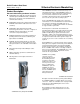
Baseplate extenders and cables provide great flexibility to
the CHARM installation in existing cabinets or in custom
enclosures. Cables are redundant, each carrying 24 VDC
field power, 6.3 VDC CHARM power and one of the
communication busses.
Bus termination provides added robustness for the
communication bus and is installed at the end of the
physical bus.