
Product data


DeltaV Product Data Sheet
October 2014 – Page 12 S-Series Electronic Marshalling
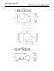
CHARM I/O Card hardware
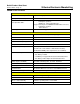
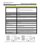
Specifications for CHARM I/O Card Carrier
Number of I/O Cards per carrier 2 (redundant pair)
Input power (redundant) +24 VDC ±10% at 12 A maximum
Redundant Ethernet connections
via replaceable IOP’s
Fiber-optic: 100BASE-FX with MTRJ connectors;
- Full duplex operation;
- Multimode - 2 km nominal distance.
Copper twisted pair: 10/100BASE-TX with RJ45 connectors;
- Full duplex operation
- 100 m distance
Mounting DIN rail Latch to T-type rail
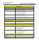
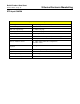
Specifications for CHARM I/O Card
Number of I/O Channels 96 Channels, Individually defined signal types
Number of I/O Clients 4 (Controllers)
Number of CIOC’s per Controller 16
Number of CIOC’s per system 300
I/O update rates 50ms, 100ms, 250ms, 500ms
CIOC power (24 VDC) 0.28 A per Redundant CIOC node
(includes two cards and two communication modules)
(individual CHARM power requirements are in addition)
CIOC Heat Dissipation 8 Watts max. per Redundant CIOC node
- 2.0 Watts per CIOC
- 1.34 Watts per Copper Ethernet I/O Communication Port
- 2.0 Watts per Fiber Optic I/O Communication Port
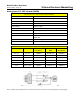
CIOC output to CHARMS 6.3 VDC redundant power, at 3.25 A maximum
*
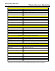
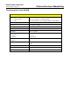
Fuse Protection (internal) Internal Non-replaceable Fuse
Mounting 2-wide CHARM I/O Carrier
Communication Redundant Ethernet connections via CHARM I/O Carrier
Network Addressing Auto Assigned during commissioning
LED Indicators:
Green – Power Indicates DC power is applied.
Red – Error Indicates an error condition.
Green – Active/Standby Indicates operating mode of each CIOC
Yellow flashing – Pri./Sec. CN Indicates valid control network communication.
*
Actual CIOC Output to CHARMs is dependent on number of installed CHARMs