IOM-DPT-A: FEB 2014 DELTA CONTROLS MANUFACTURE OF PRESSURE TRANSMITTERS AND CONTROL INSTRUMENTS USER’S MANUAL SMART TEMPERATURE TRANSMITTER type: DPT-2000ALW FEB 2014 DELTA CONTROLS LTD., Island Farm Avenue, West Molesey, Surrey, KT8 2uz tel. +44 (0) 20 8939 3570; fax +44 (0) 20 8783 1163 www.delta-controls.com, e-mail: sales@delta-controls.
Symbols used Symbol i Description Warning to proceed strictly in accordance with the information contained in the documentation in order to ensure the safety and full functionality of the device. Information particularly useful during installation and operation of the device. Information particularly useful during installation and operation of a type Ex device.
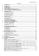
1 I. II. 1. 2. 3. 4. 5. IOM-DPT-A: FEB 2014 CONTENTS APPENDIX Exd............................................................................................................................. 2 APPENDIX Exi. ............................................................................................................................. 7 INTRODUCTION ......................................................................................................................... 11 USER MATERIALS .....................
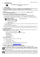
2 I. IOM-DPT-A: FEB 2014 APPENDIX Exd 1180 1453 DPT–2000ALW TEMPERATURE TRANSMITTER Exd VERSION 1. Introduction 1.1. This “Appendix Exd.01” applies to transmitters of type DPT-2000ALW in Exd versions only, marked on the rating plate as shown in 3 and denoted Exd in the Product Certificate. 1.2. The appendix contains supplementary information relating to the Exd (flame-proof) versions of mentioned transmitters. During installation and use of Exd transmitters, reference should be made to DTR.DPT.ALW.
3 IOM-DPT-A: FEB 2014 primary and secondary windings in which don’t appear voltage higher than 250V. The duty of power supply installation with above mentioned requirements rests on user. Appendix Exd.01 5.3. Measurements of operating temperature of transmitter 5.3.1.
4 IOM-DPT-A: FEB 2014 In the case of significant increase in medium temperature measurement of Tp must be executed again and again must be specified the temperature class for the gas or the maximum surface temperature combustible dust. 5.5. With regard on kind of casing material (light alloy with large aluminium content), the user is obliged to assure, that possibility of hitting casing does not step out in place of transmitter installation. 5.6.
5 IOM-DPT-A: FEB 2014 Appendix Exd.01 In danger zone don’t unscrew transmitter covers and don’t change the display position or its back lighting. In case of transmitter calibration outside danger zone is possible communicator connecting to and terminals. Transmitter is furnished in communication resistor (RD = 240Ω), closed with jumper at and terminals installed by manufacturer.
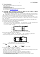
6 IOM-DPT-A: FEB 2014 Specific conditions of use: i Permissible gap of flameproof joint marked L4 is less than defined in norm EN 60079-1:2007 and cannot be greater than passed value on fig. 7. i Temperature class (T* for gases) or maximum surface temperature (T* for dust ) depends mainly on the temperature of the process (temperature of the controlled medium), and the method of installation on site.
7 II. IOM-DPT-A: FEB 2014 Appendix Exi APPENDIX Exi. 1180 1453 DPT–2000ALW TEMPERATURE TRANSMITTER Exi VERSION 1. Introduction 1.1. This “Appendix Exi” applies to transmitters of type DPT-2000ALW in Ex versions only, marked on the rating plate as shown in 2 and 3 and denoted Ex in the Product Certificate. 1.2. The appendix contains supplementary information relating to the Ex versions of these transmitters. During installation and use of Ex transmitters, reference should be made to DTR.DPT.ALW.
8 IOM-DPT-A: FEB 2014 Appendix Exi 4. User information. Together with the ordered transmitters, the user will receive: a) Product Certificate, b) Declaration of conformity c) Copy of certificate – on request d) „User’s Manual numbered: „DTR.DPT.ALW.03” with Appendix Exi.. User can find them at www.delta-controls.com 5. Permitted input parameters (based on data from the FTZÚ 14 ATEX certificate, and certification documentation).
9 IOM-DPT-A: FEB 2014 Appendix Exi 5.4. Input inductance and capacity: Ci = 20nF, Li = 1,1mH 5.5. Supply voltage min.: 13.5VDC ** 5.6. Load resistance: from 28V linear supply Ro max [Ω] = 28V – 13.5V** – (300Ω* * 0,02A) 0,023A for transmitter without display back lighting from a source with “trapezial” or “rectangular” characteristic supply Ro max [Ω] = Uzas. – 13.5V** 0,023A *) barrier resistance **) 16,5V for transmitter with display back lighting 5.7.
10 IOM-DPT-A: FEB 2014 Specific conditions of use i Allowed operating temperature range specified in point 5 Appendix Exi i Operating temperature range is restricted in the range of Ta = -20°C to 60°C if the device is operating in a Group I M1.
11 IOM-DPT-A: FEB 2014 INTRODUCTION 1.1. This Manual is intended for users of DPT-2000ALW smart temperature transmitters in normal and intrinsic-safety versions, containing the data and guidelines necessary to understand the functioning of the transmitters and how to operate them. It includes essential recommendations concerning installation and use, as well as emergency procedures.
12 i IOM-DPT-A: FEB 2014 4.1.1. The DPT-2000ALW transmitters in intrinsically safe version have additional designations, which are specified in DTR.DPT.ALW.03 Appendix Exi. 4.1.2. The DPT-2000ALW transmitters in Exd version have additional designations, which are specified in DTR.DPT.ALW.03 Appendix Exd.01. 4.2. Ordering procedure Procedure of ordering DPT-2000ALW/___/___/L=.
13 i IOM-DPT-A: FEB 2014 The value of transmitter minimal supply voltage can be calculated from the following formula: Umin = 12 + 0,023 x Ro [V] for transmitter operating without LCD display backlight (or read from the drawing below) Umin = 15 + 0,023 x Ro [V] for converter operating with LCD display backlight. (or read from the drawing below) Transmitters made in Ex version are delivered with display backlight switched off. The user can switch the backlight on by himself.
14 IOM-DPT-A: FEB 2014 5.4. Operating conditions. Ambient temperature range -40°C 85°C Operating temperature for intrinsic-safe versions (Exi) in accordance with „Appendix Exi”. Operating temperature for Exd versions in accordance with „Appendix Exd.01”. Relative humidity Medium temperature range up to 98% Pt100 - 200 ... 550 °C N-Cr-NiAl - 40 ... 550 °C Thermal compensation range -25 … 75 0C 5.4.1.
15 IOM-DPT-A: FEB 2014 5.4.5. Insulation Resistance >100 MΩ @110V transmitters with gas arresters >100 MΩ @750V DC transmitters without gas arresters (Exi) 5.4.6. High Voltage Test 500V AC, or 750V DC, 1min, transmitters without gas arresters (Ex applications) 75V AC, or 110V DC, 1min, transmitters with gas arresters 5.4.7. Enclosure ingress protection EN 60529, IP 66,67 5.5.
16 IOM-DPT-A: FEB 2014 6.2.1. Transmitter casing A casing of DPT... transmitter is made of high-pressure casting of aluminium alloy or 316L steel. It consists of a body, two bolted side covers (full and with pane), cable inlets and plug with M20x1,5 or ½ NPT thread. Inside the casings is divided into two chambers, separated by a header. An additional header, with a ribbon cable is intended for transmitting a signal from temperature sensor to the inside of a transmitter.
17 IOM-DPT-A: FEB 2014 8.3. Protection from excess voltage 8.3.1. The transmitters may be in danger from excess voltage caused by connection faults or atmospheric electrical discharge. Protection from excess voltage between the wires of the transmission line is provided by TVS diodes installed in all types of transmitter (see the table, column 2). 8.3.2.
18 IOM-DPT-A: FEB 2014 9.2. Configuration and Calibration 9.2.1. The transmitter has features which enable metrological and identification parameters to be set and altered. The configurable metrological parameters affecting the transmitter’s output current include the following: a. lower end-point of the set range b. upper end-point of the set range c. unit d. time constant e. type of characteristic curve: linear or radical f. decimal index 9.2.2.
19 IOM-DPT-A: FEB 2014 | EXIT (First announcement which will see after inclusion of Menu Local. | If you will confirm this option, you will go out from Local Menu | and you will come back to continue of measuring) | SET LRV_________ (The Setting of the range of the set LRV beginning) | \ | BACK (Return to Local Menu.
20 IOM-DPT-A: FEB 2014 DAMPING________ | \ | BACK | | | | | | | | | | | 0 [S] | 2 [S] | 5 [S] | 10 [S] | 30 [S] | (Setting of the solid temporary suppression of the process variable) TRANSFEr_______ | \ | BACK | | | | | | | | | | | LINEAR | SQRT | SQRTX^3 | SQRTX^5 | SPECIAL | SQUARE | (Setting of the current output form) LCD1VARiable____ | \ | BACK | | | | | | | | | | | | | CURRENT | | | PERCENT | (Type of the process variable displayed on LCD1) (Return to Local Menu.
21 IOM-DPT-A: FEB 2014 LCD2VARiable____ | \ | BACK | | | | | | | | | | | | | TEMPERATURE | | | USER | | | UNIT | | | | | NO UNIT | | (Type of the process variable displayed on LCD2) LCD2 DP_________ | \ | BACK | | | | | | | | | | | | | XXXXX• | | XXXX•X | | XXX•XX | | XX•XXX | | •XXXXX | (The process variable point position on LCD2) FACTORY________ | \ | BACK | | | | | | | | | | | | | RECALL | (Come back to factory setting) RESET__________ | \ | \ | BACK | | | | | | | | | RESET (The program enf
22 MID_WP_________ | \ | BACK | | | | | | | | | | | | | | | ON | | | OFF IOM-DPT-A: FEB 2014 (Lock modify the parameters associated with MID) (Back to the Local Menu. If you approve this option, return back to the main menu Tree Local) (Submit one of the following through constant ◙ pressing.
23 IOM-DPT-A: FEB 2014 9.2.5.1. Setting up a local LCD display The LCD display configuration can do in dependence from needs. Changes of the display options in local MENU are possible using buttons or remote way using communicator, or the PC software. If it is necessary the display switching off is also possible. The display switching of function is possible with using communicator or PC software only. There 3 main displays are visible: LCD1 – the current or guidance percent preset range display.
24 IOM-DPT-A: FEB 2014 9.3. Calibration. The transmitter can be calibrated with reference values of the standard operating temperature sensor transmitter to its scale (calibration input) or to current output 4 ... 20 (20 ... 4) mA - (current calibration). The values set calibration points need not be equal to the upper and lower limit of the basic range. But they can not exceed out up and down. The width of the calibration range shall not be less than the minimum width of the setting range.
25 IOM-DPT-A: FEB 2014 14. FIGURES. Memory Sensing module Input circuit Converter a/c 1 or ess roc Output circuit P + D Noise filter Power supply/ measurement system _ 2 Load resistance min.250 Communicator Modem Fig.1. DPT... transmitters – block diagram. For successful communication with transmitter the resistance in measuring loop, behind connected device to communication, should be higher than 250Ω. If necessary install the additional resistor in the line.
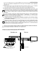
26 IOM-DPT-A: FEB 2014 RS 232 APT2000 D-SOFT Configurator BELL 202 JUMPER 4÷20 mA F2 F3 F4 RE PV F4 ABC DEF GHI @%& JKL MNO PQR +/ STU VWX YZ# . 7 4 1 8 5 2 9 0 6 3 * 240 _ To measure the transmitter current without disconnecting the measuring loop, connect a milliammeter to control terminals and . Communicator F1 PF + SIGNAL Ro -TEST +TEST mA Power supply + Current loop Fig.2b.
27 IOM-DPT-A: FEB 2014 RS 232 APT2000 DPT2000 D-SOFT Configurator Configurator BELL 202 JUMPER 4÷20 mA F1 F2 F3 F4 PF RE PV F4 ABC DEF GHI @%& JKL MNO PQR +/ STU VWX YZ# . 7 4 1 8 5 2 9 6 3 0 * 240 _ -TEST + SIGNAL Ro Communicator +TEST mA Power supply + Current loop Fig.2d. The link of transmitter and communicator or modem to transmitter terminals in Rys. 2d case of the resistance in current loop is smaller than 250Ω.
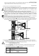
28 The electronic circuits and display side 240 Packing gland M20x1,5 lub 1/2 NPT cable 101,5 The electrical terminals side + SIGNAL -TEST 133 18 +TEST 132 FIELD TERMINALS 18 IOM-DPT-A: FEB 2014 Earthing terminal Lock preventing rotation of the casing 165 M20x1,5 or G1/2" L M20x1,5 or G1/2" L L 150 Fitting socket M20x1,5 or G1/2" O6 Fig.3.
29 ±180o with 900 pitch IOM-DPT-A: FEB 2014 przewody wires unscrew the display cover and casing display screws Configuration buttons Move the electronic unit from transmitter casing, take up Rys. 4 the upper part of the casing with display from the catch and revolve its to left or to right to the display setting at needed position. Rotation possibility ±1800 with 90° pitch. Screw on the display unit screws and display cover Fig.4. DPT... display rotation possibility, configuration buttons.
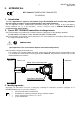
30 IOM-DPT-A: FEB 2014 Thermowell Excision for key 24mm Fig.6. The types of shields of measuring insert.
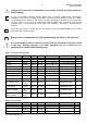
31 IOM-DPT-A: FEB 2014 L6 L7 A L5 A-A L8 B B L4 A B-B Scale:2:1 L4 MINIMUM WIDTH OF JOINT AND MAXIMUM GAP FOR GROUP IIC ENCLOSURES Nr diameter width of joint (min. real) L [mm] D [mm] +0,027 d [mm] -0,040 O15 -0,070 D-d [mm] quantity of joint minimum according to PN-EN 60079-1:2008 L4 13,3 O15 2 width of joint min.12,5 L5 12 M72x1,5 M72x1,5 2 L6 9 M20x1,5 M20x1,5 2 L7 12,7 1/2NPT 1/2NPT 2 L8 10 min.5 threads engaged(8) min.5 threads engaged(6) min.
32 IOM-DPT-A: FEB 2014 KE EP COV E R T I G HT L CIRCUIT IS ALIVE E IV WARNING- RCU I T S A CI Fig.8. How to lead the casing of DPT-2000ALW transmitter.
33 IOM-DPT-A: FEB 2014