
Non-Combustible Ceiling Installation Instructions

Ceilin
Information is subject to change without notice or obligation. M-54740 Rev. D
Notes: Dimensions donated by ( ) are in millimeters.
Ceiling Radiation Damper
ITG-CRD
Non-Combustible Ceiling Installation Instructions
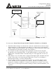
5. The penetration in the ceiling should be located within the ceiling tiles or panels without
necessitating cuts in the ceiling suspension main runners or cross tees. If a cut is needed, a
maximum of one runner or cross tee may be cut to enable proper damper location and
installation. Each cut end shall be supported by a min 12 SWG (2.7) vertical hanger wire.
The opening in the ceiling should be the same size as the outside of the damper frame.
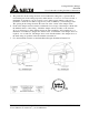
6. Position the damper and fan assembly such that the bottom edge of the damper is flush with
the finished surface of the ceiling. Attach the damper and fan assembly to the structure
above or adjacent to it. If the damper and fan are being attached to the assembly above, a
minimum of 12 SWG (2.7) hangar wire must be used. A minimum of four hanger wires are
required, one on each side. The hanger wires can be attached either to the damper sleeve or
the fan housing as specified in the fan installation instructions.
7. For other installation details see the Delta Breez Integrity Installation Instructions.