
Installation & Operating Manual

MODELS:
GBR80HLED,
GBR
80
LED,
GBR80MHLED
,
GBR100HLED
,
GBR
100
LED
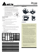
SUPPLIED ACCESSORIES
Part name Appearance Quantity
Grille 1
Fan 1
Housing 1
Duct Connector
(4’’)
1
Long Wood Screw
(ø4×25)
8
Machine Screw
(#8-32x5/16’’)
4
Suspension Bracket
4
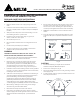
INSTALLATIONS
Proper insulation around the fan to minimize building heat loss and
gain. 4’’ circular duct is recommended for installation. The ducting
from this fan to the outside of the building has a strong effect on
the air flow, noise and energy use of the fan. Use the shortest,
straightest duct routing possible for best performance, and avoid
installing the fan with smaller ducts than recommended. Insulation
around the ducts can reduce energy loss and inhibit mold growth.
Fans installed with existing ducts may not achieve their rated air
flow.
Roof cap
(with built-in damper)
Seal gap
around
housing
Caulk termination
to duct
Fan housing
Short piece of flexible
duct helps alignment
and absorbs sound
Wall cap
(with built-in damper)
or
MOUNT
MOUNTMOUNT
MOUNT
HOUSING
HOUSINGHOUSING
HOUSING
WITH
WITHWITH
WITH
FLANGE:
FLANGE:FLANGE:
FLANGE:
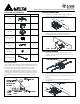
1. To bend the housing tabs out to 90 degree and make
housing tabs contact the bottom of the joist.
Joist
Tabs
2. The housing mounts with 4 long wood screw (Ø4×25).
Screw housing to joist through lowest holes in each
mounting flange, then through the other holes.
Joist
Long Wood Screw
( 4×25)
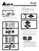
USING SUSPENSION BRACKETS
USING SUSPENSION BRACKETS USING SUSPENSION BRACKETS
USING SUSPENSION BRACKETS
3. Sliding suspension brackets available to allow for your
specific
positioning of housing anywhere between joists
and span up to 24’’.
Suspension Bracket
4. Extend suspension brackets to the width of the joists. Make
sure the fan body is level and perpendicular with the joist.
5. Secure suspension brackets to joists with long wood screw
(ø4×25).
6. Secure suspension brackets together with machine screw
(#8-32x5/16’’).
(#8-32x5/16”)
Joist
Joist