
Installation guide
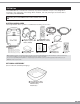


2. Connect the supplied power cable to the vehicle
electrical system, tapping into an accessory
hot line, constant battery line, and ground.
3. Verify that all system functions operate
properly before final mounting. Refer to the
Delphi Mobile Video DVDM-800 User Manual
for detailed operating information.
AV 2 In
External Audio/Video
Display Device
External Audio/Video
Input Device
External Audio/Video
Input Device
External
Audio/Video
Input Device
V
AV Out
AV In
R
L
V
R
L
S-V
R
L
POSITIVE/NEGATIVE SYSTEM
POSITIVE SYSTEM
Purple/Ground
Blue/12V
Green/Door Trigger
FM
Transmitter
Yellow/Battery
Black/Ground
RVDC/Acc
16
15
14
13
12
11
10
9
16 Pin Line
Power/Harness
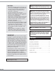
ELECTRICAL CONNECTIONS
1. Connect the power cable and A/V components
to the appropriate vehicle electrical connections
(Figure 3):
a. Insert the 16-pin mini-DIN connector into
the mini-DIN connector on the back of the
system.
b. Route A/V lead through vehicle, avoiding
sharp edges and rub points, to location of
A/V input/output box.
6
1
1
3
2
2
3
NEGATIVE SYSTEM
Purple/12V
Blue/Ground
Green/Door Trigger
1
2
3
Video 1 In
Gnd
Video Out
Gnd
Audio L Out
Audio R Out
Audio 2 L In
Audio 2 R In
1
2
3
4
5
6
7
8
S Video In C
Gnd
Gnd
S Video in Y
Gnd
Gnd
Audio 1 L In
Audio 1 R In
Warning: Failure to properly follow these instructions
could result in damage to the vehicle, its electronic system,
other property, or personal injury and/or death.
Figure 3.