
Integration Guide


Table Of Contents
- Preface
- Contents
- 1 System description
- 1.1 Overview
- 1.2 Architecture
- 1.3 Pin-out
- 1.4 Operating modes
- 1.5 Power management
- 1.6 System functions
- 1.7 RF connection
- 1.8 SIM interface
- 1.9 Serial Communication
- 1.10 Audio
- 1.11 ADC input (LEON-G100 only)
- 1.12 General Purpose Input/Output (GPIO)
- 1.13 M2M Setup Schematic Example
- 1.14 Approvals
- 2 Design-In
- 3 Handling and soldering
- 4 Product Testing
- Appendix
- A Extra Features
- B Glossary
- Related documents
- Revision history
- Contact
LEON-G100/G200 - System Integration Manual
GSM.G1-HW-09002-F3 Preliminary Design-In
Page 82 of 101
2.4.1 Antenna termination
LEON-G100/G200 modules are designed to work on a 50 Ω load. However, real antennas have no perfect 50 Ω
load on all the supported frequency bands. To reduce as much as possible performance degradation due to
antenna mismatch, the following requirements should be met:
Measure the antenna termination with a network analyzer: connect the antenna through a coaxial cable to
the measurement device, the |S
11
| indicates which portion of the power is delivered to antenna and which
portion is reflected by the antenna back to the modem output
A good antenna should have a |S
11
| below -10 dB over the entire frequency band. Due to miniaturization,
mechanical constraints and other design issues, this value will not be achieved. A value of |S
11
| of about -6
dB - (in the worst case) - is acceptable
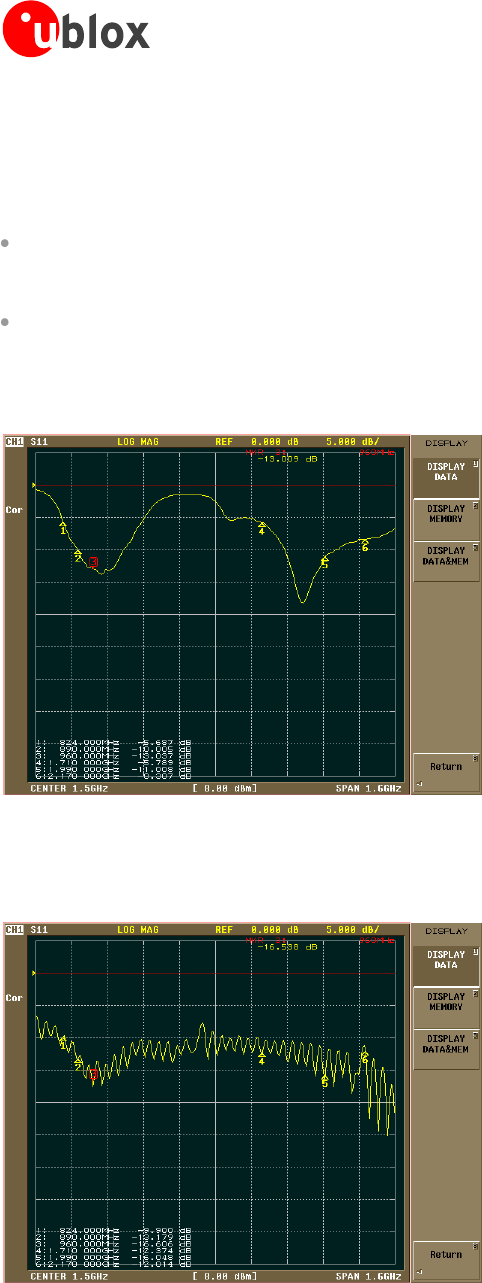
Figure 49 shows an example of this measurement:
Figure 49: |S
11
| sample measurement of a penta-band antenna that covers in a small form factor the 4 GSM bands (850 MHz, 900
MHz, 1800 MHz and 1900 MHz) and the UMTS Band I
Figure 50 shows comparable measurements performed on a wideband antenna. The termination is better, but
the size of the antenna is considerably larger.
Figure 50: |S
11
| sample measurement of a wideband antenna