
Integration Guide


Table Of Contents
- Preface
- Contents
- 1 System description
- 1.1 Overview
- 1.2 Architecture
- 1.3 Pin-out
- 1.4 Operating modes
- 1.5 Power management
- 1.6 System functions
- 1.7 RF connection
- 1.8 SIM interface
- 1.9 Serial Communication
- 1.10 Audio
- 1.11 ADC input (LEON-G100 only)
- 1.12 General Purpose Input/Output (GPIO)
- 1.13 M2M Setup Schematic Example
- 1.14 Approvals
- 2 Design-In
- 3 Handling and soldering
- 4 Product Testing
- Appendix
- A Extra Features
- B Glossary
- Related documents
- Revision history
- Contact
LEON-G100/G200 - System Integration Manual
GSM.G1-HW-09002-F3 Preliminary System description
Page 63 of 101
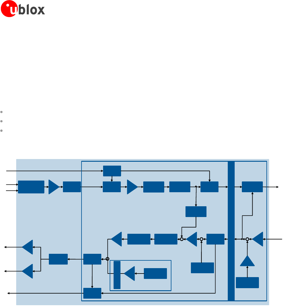
1.10.3 Voice-band processing system
The digital voice-band processing on the LEON-G100/G200 is implemented in the DSP core inside the baseband
chipset. The analog audio front-end of the chipset is connected to the digital system through 16 bit ADC
converters in the uplink path, and through 16 bit DAC converters in the downlink path. The digitized TX and RX
voice-band signals are both processed by digital gain stages and decimation filter in TX, interpolation filters in RX
path. The processed digital signals of TX and RX are connected to the DSP for various tasks (i.e. speech codec,
digital mixing and sidetone, audio filtering) implemented in the firmware modules.
External digital audio devices can be interfaced to the DSP voice-band processing system via the I
2
S interface.
The voice-band processing system can be split up into three different blocks:
Sample-based Voice-band Processing (single sample processed at 8 kHz, every 125 µs)
Frame-based Voice-band Processing (frames of 160 samples are processed every 20 ms)
MIDI synthesizer running at 47.6 kHz
These three blocks are connected by buffers and sample rate converters (for 8 to 47.6 kHz conversion)
Multiplexer
Switch
DAC
Switch
ADC
I2S_RXD I2Sy RX
Switch
MIC 1
MIC 2
Uplink
Analog Gain
Uplink
filter 2
Uplink
filter 1
Hands-
free
To Radio
TX
Scal_Mic
Digital Gain
Sidetone
Downlink
filter 1
Downlink
filter 2
MIDI
player
SPK_P/N
HS_P
HS
Analog_gain
Switch
Switch
I2Sx TX
I2S_TXD
Scal_Rec
Digital Gain
Mix_AFE
Digital Gain
SPK
Analog_gain
Gain_out
Digital Gain
Tone
Generator
Switch
I2Sy TX
From
Radio RX
Speech
level
I2Sx RX
Sample Based Processing Frame Based
Processing
AMR
Player
Circular buffer
Voiceband Sample Buffer
Figure 40: LEON-G100/G200 voice-band processing system block diagram
The sample-based voice-band processing main task is to transfer the voice-band samples from either analog
audio front-end TX path or I2Sx RX path to the Voice-band Sample Buffer and from the Voice-band Sample
Buffer to the analog audio front-end RX path and/or I2Sx TX path.
While doing this the samples are scaled by digital gains and processed by digital filters both in the uplink and
downlink direction. The sidetone is generated mixing scaled uplink samples to the downlink samples. The frame-
based voice-band processing implements the Hands Free algorithm. This consists of the Echo Canceller, the
Automatic Gain Control and the Noise Suppressor. Hands Free algorithm acts on the uplink signal only. The
frame-based voice-band processing also implements an AMR player (according to RFC3267 standard). AMR
player supported data rates are: 12.2 – 10.2 – 7.95 – 7.40 – 6.70 – 5.90 – 5.15 – 4.75 kbps. The speech uplink
path final block before radio transmission is the speech encoder. Symmetrically, on downlink path, the starting
block is the speech decoder which extracts speech signal from the radio receiver.
The circular buffer is a 3000 word buffer to store and mix the voice-band samples from Midi synthesizer. The
buffer has a circular structure, so that when the write pointer reaches the end of the buffer, it is wrapped to the
begin address of the buffer.