
Integration Guide
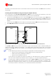

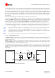


Table Of Contents
- Preface
- Contents
- 1 System description
- 1.1 Overview
- 1.2 Architecture
- 1.3 Pin-out
- 1.4 Operating modes
- 1.5 Power management
- 1.6 System functions
- 1.7 RF connection
- 1.8 SIM interface
- 1.9 Serial Communication
- 1.10 Audio
- 1.11 ADC input (LEON-G100 only)
- 1.12 General Purpose Input/Output (GPIO)
- 1.13 M2M Setup Schematic Example
- 1.14 Approvals
- 2 Design-In
- 3 Handling and soldering
- 4 Product Testing
- Appendix
- A Extra Features
- B Glossary
- Related documents
- Revision history
- Contact
LEON-G100/G200 - System Integration Manual
GSM.G1-HW-09002-F3 Preliminary System description
Page 60 of 101
1.10.1.6 Connection to an external analog audio device
When the LEON-G100/G200 module analog audio output has to be connected to an external audio device,
HS_P analog audio output can be used.
A 10 µF series capacitor (e.g. Murata GRM188R60J106M) must be inserted between the HS_P output and
the single ended analog input of the external audio device (to decouple the bias)
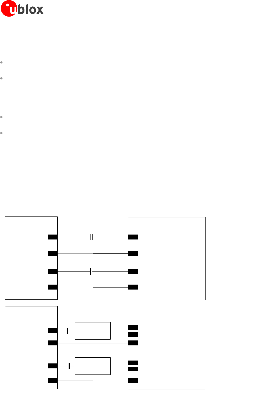
An additional single ended to differential circuit is required for audio devices with a differential analog input.
The signal levels can be adapted by setting gain using AT commands, but additional circuitry must be
inserted if the HS_P output level of the module is too high for the input of the audio device
If LEON-G100/G200 module analog audio input has to be connected to an external audio device, MIC_BIAS1/
MIC_GND1 can be used (default analog audio input of the module).
Insert a 10 µF series capacitor (e.g. Murata GRM188R60J106M) between the single ended analog output of
the external audio device and MIC_BIAS1
Connect the reference of the single ended analog output of the external audio device to MIC_GND1. If the
external audio device is provided with a differential analog output, insert an additional differential to single
ended circuit. The signal levels can be adapted by setting gain using AT commands, but additional circuitry
must be inserted if the output level of the audio device is too high for MIC_BIAS1
Examples of connecting LEON-G100/G200 modules to external audio applications are illustrated in the Figure 39
and Table 25.
To enable the audio path corresponding to these input/output, please refer to u-blox 2G GSM/GPRS AT
Commands Manual [2], AT+USPM command.
To tune audio levels for the external device please refer to u-blox 2G GSM/GPRS AT Commands Manual [2],
AT+USGC, AT+UMGC commands.
LEON-G100/G200
C1
37
HS_P
43
MIC_GND1
44
MIC_BIAS1
Single-ended Analog Input
Single-ended Analog Output
C2
Audio Device
Reference
GND
Reference
LEON-G100/G200
37
HS_P
43
MIC_GND1
44
MIC_BIAS1
Positive Analog Input
Positive Analog Output
C3
Audio Device
Reference
GND
Reference
Negative Analog Output
Differential to
Single-ended
Negative Analog Input
Single-ended
to Differential
C4
Figure 39: Application circuits to connect the LEON module to external audio devices with proper single-ended or differential
analog audio inputs/outputs