
Integration Guide
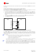

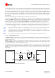


Table Of Contents
- Preface
- Contents
- 1 System description
- 1.1 Overview
- 1.2 Architecture
- 1.3 Pin-out
- 1.4 Operating modes
- 1.5 Power management
- 1.6 System functions
- 1.7 RF connection
- 1.8 SIM interface
- 1.9 Serial Communication
- 1.10 Audio
- 1.11 ADC input (LEON-G100 only)
- 1.12 General Purpose Input/Output (GPIO)
- 1.13 M2M Setup Schematic Example
- 1.14 Approvals
- 2 Design-In
- 3 Handling and soldering
- 4 Product Testing
- Appendix
- A Extra Features
- B Glossary
- Related documents
- Revision history
- Contact
LEON-G100/G200 - System Integration Manual
GSM.G1-HW-09002-F3 Preliminary System description
Page 59 of 101
Hands-free functionality is implemented using appropriate DSP algorithms for voice-band handling (echo
canceller and automatic gain control), managed via software (Refer to u-blox 2G GSM/GPRS AT Commands
Manual [2]; AT+UHFP command).
In this mode the main downlink audio path must be “Loudspeaker”, the main uplink audio path can be
“Handset microphone” or “Headset microphone” (refer to u-blox 2G GSM/GPRS AT Commands Manual [2];
AT+USPM command: <main_uplink>, <main_downlink> parameters). Use of an uplink audio path for
hands-free makes it unavailable for another device (handset/headset). Therefore:
Microphone can be connected to the input pins MIC_BIAS1/MIC_GND1 or MIC_BIAS2/MIC_GND2
High power loudspeaker must be connected to the output pins SPK_P/SPK_N
The default parameters for audio uplink profiles “Handset microphone” and “Headset microphone”
(refer to u-blox 2G GSM/GPRS AT Commands Manual [2]; AT+UMGC, AT+UUBF, AT+UHFP) are for a
handset and a headset microphone. To implement hands-free mode, these parameters should be
changed on the audio path corresponding to the connection chosen. Procedure to tune parameters for
hands-free mode (gains, echo canceller) can be found in LEON Audio Application Note [12].
When hands-free mode is enabled, the audio output signal on HS_P is disabled.
The physical width of the high-power audio outputs lines on the application board must be wide
enough to minimize series resistance.
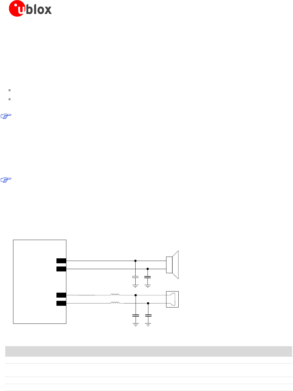
Figure 38 shows an application circuit for hands-free mode. In this example the LEON-G100/G200 modules are
connected to an 8 Ω speaker and a 2.2 kΩ electret microphone. Insert an 82 nH series inductor (e.g. Murata
LQG15HS82NJ02) on each microphone line, and a 27 pF bypass capacitor (e.g. Murata GRM1555C1H270J) on
all audio lines to minimize RF coupling and the TDMA noise.
LEON-G100/G200
SPK
C1 C2
L2
L1
MIC
C3 C4
39
SPK_N
38
SPK_P
43
MIC_GND1
44
MIC_BIAS1
Figure 38: Hands free mode application circuit
Reference
Description
Part Number - Manufacturer
C1, C2, C3, C4
27 pF Capacitor Ceramic COG 0402 5% 25 V
GRM1555C1H270JZ01 - Murata
L1, L2
82nH Multilayer inductor 0402
(self resonance frequency ~1 GHz)
LQG15HS82NJ02 - Murata
SPK
Loudspeaker
MIC
Active Elected Microphone
Table 24: Example of components for hands-free connection