
Integration Guide
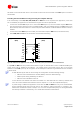

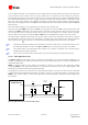


Table Of Contents
- Preface
- Contents
- 1 System description
- 1.1 Overview
- 1.2 Architecture
- 1.3 Pin-out
- 1.4 Operating modes
- 1.5 Power management
- 1.6 System functions
- 1.7 RF connection
- 1.8 SIM interface
- 1.9 Serial Communication
- 1.10 Audio
- 1.11 ADC input (LEON-G100 only)
- 1.12 General Purpose Input/Output (GPIO)
- 1.13 M2M Setup Schematic Example
- 1.14 Approvals
- 2 Design-In
- 3 Handling and soldering
- 4 Product Testing
- Appendix
- A Extra Features
- B Glossary
- Related documents
- Revision history
- Contact
LEON-G100/G200 - System Integration Manual
GSM.G1-HW-09002-F3 Preliminary System description
Page 57 of 101
Audio pins ESD rating is 1 kV (contact discharge). A higher protection level could be required if the lines
are externally accessible on the application board. A higher protection level can be achieved mounting
an ESD protection (e.g. EPCOS CA05P4S14THSG varistor array) on the lines connected to these pins if
they are externally accessible on the application board.
If the audio pins are not used, they can be left floating on the application board.
1.10.1.3 Handset mode
Handset mode is the default audio operating mode of LEON-G100/G200 modules. In this mode the main uplink
audio path is “Handset microphone”, the main downlink audio path is “Normal earpiece” (refer to u-blox 2G
GSM/GPRS AT Commands Manual [2]; AT+USPM command: <main_uplink>, <main_downlink> parameters).
Handset microphone must be connected to inputs MIC_BIAS1/MIC_GND1
Handset receiver must be connected to output HS_P
Figure 36 shows an example of an application circuit connecting a handset (with a 2.2 kΩ electret microphone
and a 32 Ω receiver) to the LEON-G100/G200 modules. The following actions should be done on the application
circuit:
Mount a series capacitor on the HS_P line to decouple the bias
Mount a 10 µF ceramic capacitor (e.g. Murata GRM188R60J106M) if connecting a 32 Ω receiver, or a load
with greater impedance (such as a single ended analog input of a codec). Otherwise if a 16 Ω receiver is
connected to the line, a ceramic capacitor with greater nominal capacitance must be used: a 22 µF series
capacitor (e.g. Murata GRM21BR60J226M) is required
Mount a 82 nH series inductor (e.g. Murata LQG15HS82NJ02) on each microphone line and a 27 pF bypass
capacitor (e.g. Murata GRM1555C1H270J) on all audio lines to minimize RF coupling and TDMA noise
LEON-G100/G200
C1
AUDIO
HANDSET
CONNECTOR
C2 C3
J1
4
3
2
1
L1
L2
37
HS_P
43
MIC_GND1
44
MIC_BIAS1
C4
D1
Figure 36: Handset connector application circuit
Reference
Description
Part Number - Manufacturer
C1, C2, C3
27 pF Capacitor Ceramic COG 0402 5% 25 V
GRM1555C1H270JZ01 - Murata
C4
10 µF Capacitor Ceramic X5R 0603 20% 6.3V
GRM188R60J106M - Murata
L1, L2
82 nH Multilayer inductor 0402
(self resonance frequency ~1 GHz)
LQG15HS82NJ02 - Murata
J1
Audio Handset Jack Connector, 4Ckt (4P4C)
52018-4416 - Molex
D1
Varistor Array for ESD protection
CA05P4S14THSG - EPCOS
Table 22: Example of components for handset connection
1.10.1.4 Headset mode
The audio path is automatically switched from handset mode to headset mode when a rising edge is detected by
the module on HS_DET pin. The audio path returns to the handset mode when the line returns to low level.