
Integration Guide
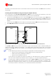

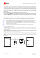


Table Of Contents
- Preface
- Contents
- 1 System description
- 1.1 Overview
- 1.2 Architecture
- 1.3 Pin-out
- 1.4 Operating modes
- 1.5 Power management
- 1.6 System functions
- 1.7 RF connection
- 1.8 SIM interface
- 1.9 Serial Communication
- 1.10 Audio
- 1.11 ADC input (LEON-G100 only)
- 1.12 General Purpose Input/Output (GPIO)
- 1.13 M2M Setup Schematic Example
- 1.14 Approvals
- 2 Design-In
- 3 Handling and soldering
- 4 Product Testing
- Appendix
- A Extra Features
- B Glossary
- Related documents
- Revision history
- Contact
LEON-G100/G200 - System Integration Manual
GSM.G1-HW-09002-F3 Preliminary System description
Page 56 of 101
First microphone input:
MIC_BIAS1: single ended supply to the first microphone and represents the microphone signal input
MIC_GND1: local ground for the first microphone
Second microphone input:
MIC_BIAS2: single ended supply to the second microphone and represents the microphone signal input
MIC_GND2: local ground for the second microphone
For a description of the internal function blocks see Figure 40.
1.10.1.2 Downlink path (speaker outputs)
The RX (downlink) path of the analog audio front-end of the module consists of two speaker outputs available
on the following pins:
First speaker output:
HS_P: low power single ended audio output. This pin is internally connected to the output of the single
ended audio amplifier of the chipset
Second speaker output:
SPK_N/SPK_P: high power differential audio output. These two pins are internally connected to the
output of the high power differential audio amplifier of the chipset
See Figure 40 for a description of the internal function blocks.
Warning: excessive sound pressure from headphones can cause hearing loss.
Detailed electrical characteristics of the low power single-ended audio receive path and the high power
differential audio receive path can be found in LEON-G100/G200 Data Sheet [1].
Table 21 lists the signals related to analog audio functions.
Name
Description
Remarks
HS_DET
Headset detection input
Internal active pull-up to 2.85 V enabled.
HS_P
First speaker output with low power single-ended
analog audio
This audio output is used when audio downlink path is
“Normal earpiece“ or “Mono headset“
SPK_P
Second speaker output with high power differential
analog audio
This audio output is used when audio downlink path is
“Loudspeaker“.
SPK_N
Second speaker output with power differential
analog audio output
This audio output is used when audio downlink path is
“Loudspeaker“.
MIC_BIAS2
Second microphone analog signal input and bias
output
This audio input is used when audio uplink path is set as
“Headset Microphone“. Single ended supply output and
signal input for the second microphone.
MIC_GND2
Second microphone analog reference
Local ground of second microphone. Used for “Headset
microphone” path.
MIC_GND1
First microphone analog reference
Local ground of the first microphone. Used for “Handset
microphone” path
MIC_BIAS1
First microphone analog signal input and bias output
This audio input is used when audio uplink path is set as
“Handset Microphone“. Single ended supply output and
signal input for first microphone.
Table 21: Analog Audio Signal Pins
All audio lines on an Application Board must be routed in pairs, be embedded in GND (have the ground
lines as close as possible to the audio lines), and maintain distance from noisy lines such as VCC and
from components such as switching regulators.