
Integration Guide
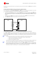

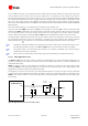


Table Of Contents
- Preface
- Contents
- 1 System description
- 1.1 Overview
- 1.2 Architecture
- 1.3 Pin-out
- 1.4 Operating modes
- 1.5 Power management
- 1.6 System functions
- 1.7 RF connection
- 1.8 SIM interface
- 1.9 Serial Communication
- 1.10 Audio
- 1.11 ADC input (LEON-G100 only)
- 1.12 General Purpose Input/Output (GPIO)
- 1.13 M2M Setup Schematic Example
- 1.14 Approvals
- 2 Design-In
- 3 Handling and soldering
- 4 Product Testing
- Appendix
- A Extra Features
- B Glossary
- Related documents
- Revision history
- Contact
LEON-G100/G200 - System Integration Manual
GSM.G1-HW-09002-F3 Preliminary System description
Page 55 of 101
1.10 Audio
LEON-G100/G200 modules provide four analog and one digital audio interfaces:
Two microphone inputs:
First microphone input can be used for direct connection of the electret condenser microphone of a
handset. This input is used when the main uplink audio path is “Handset Microphone” (refer to u-blox
2G GSM/GPRS AT Commands Manual [2]; AT+USPM command: <main_uplink> parameter)
Second microphone input can be used for direct connection of the electret condenser microphone of a
headset. This input is used when the main uplink audio path is “Headset Microphone” (refer to u-blox
2G GSM/GPRS AT Commands Manual [2]; AT+USPM command: <main_uplink> parameter)
Two speaker outputs:
First speaker output is a single ended low power audio output that can be used to directly connect the
receiver (earpiece) of a handset or a headset. This output is used when the main downlink audio path is
“Normal earpiece” or “Mono headset” (refer to u-blox 2G GSM/GPRS AT Commands Manual [2];
AT+USPM command: <main_downlink> parameter). These two downlink path profiles use the same
physical output but have different sets of audio parameters (Refer to u-blox 2G GSM/GPRS AT
Commands Manual [2]: AT+USGC, AT+UDBF, AT+USTN commands)
Second speaker output is a differential high power audio output that can be used to directly connect a
speaker or a loud speaker used for ring-tones or for speech in hands-free mode. This output is used
when audio downlink path is “Loudspeaker” (refer to u-blox 2G GSM/GPRS AT Commands Manual [2];
AT+USPM command, <main_downlink> and <alert_sound> parameters)
Headset detection input:
If enabled, causes the automatic switch of uplink audio path to “Headset Microphone” and downlink
audio path to “Mono headset”. Enabling/disabling the detection can be controlled by parameter
<headset_indication> in AT+USPM command (refer to u-blox 2G GSM/GPRS AT Commands Manual [2])
I
2
S digital audio interface:
This path is selected when parameters <main_uplink> and <main_downlink> in AT+USPM command
(refer to u-blox 2G GSM/GPRS AT Commands Manual [2]) are respectively “I
2
S input line” and “I
2
S
output line”
Not all combinations of Input-Output audio paths are allowed. Please check audio command AT+USPM
in u-blox 2G GSM/GPRS AT Commands Manual [2] for allowed combinations of audio path and for their
switching during different use cases (speech/alert tones).
The default values for audio parameters tuning commands (Refer to u-blox 2G GSM/GPRS AT
Commands Manual [2]; AT+UMGC, AT+UUBF, AT+UHFP, AT+USGC, AT+UDBF, AT+USTN commands)
are tuned for audio device connected as suggested above (i.e. Handset microphone connected on first
microphone input, headset microphone on second microphone input). For a different connection, (i.e.
connection of a Hands Free microphone) these parameters should be changed on the audio path
corresponding to the connection chosen.
1.10.1 Analog Audio interface
1.10.1.1 Uplink path (microphone inputs)
The TX (uplink) path of the analog audio front-end on the module consists of two identical microphone circuits.
Two electret condenser microphones can be directly connected to the two available microphone inputs.
The main required electrical specifications for the electret condenser microphone are 2.2 k as maximum output
impedance at 1 kHz and 2 V maximum standard operating voltage.
Board-to-board pins related to the uplink path (microphones inputs) are: