
Integration Guide
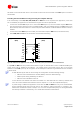


Table Of Contents
- Preface
- Contents
- 1 System description
- 1.1 Overview
- 1.2 Architecture
- 1.3 Pin-out
- 1.4 Operating modes
- 1.5 Power management
- 1.6 System functions
- 1.7 RF connection
- 1.8 SIM interface
- 1.9 Serial Communication
- 1.10 Audio
- 1.11 ADC input (LEON-G100 only)
- 1.12 General Purpose Input/Output (GPIO)
- 1.13 M2M Setup Schematic Example
- 1.14 Approvals
- 2 Design-In
- 3 Handling and soldering
- 4 Product Testing
- Appendix
- A Extra Features
- B Glossary
- Related documents
- Revision history
- Contact
LEON-G100/G200 - System Integration Manual
GSM.G1-HW-09002-F3 Preliminary System description
Page 53 of 101
To be complaint with the I
2
C bus specifications, the module pads of the bus interface are open drain output and
pull up resistors must be used. Since the pull-up resistors are not mounted on the module, they must be
mounted externally. Resistor values must conform to the I
2
C bus specifications [8]. If LEON-G100/G200 modules
are connected through the DDC bus to a single u-blox GPS receiver only (only one device is connected on the
DDC bus), use a pull-up resistor of 4.7 k . Pull-ups must be connected to a supply voltage of 2.85 V (typical),
since this is the voltage domain of the DDC pins (for detailed electrical characteristics see the LEON-G100/G200
Data Sheet [1]).
DDC Slave-mode operation is not supported, the module can act as master only.
Two lines, serial data (SDA) and serial clock (SCL), carry information on the bus. SCL is used to synchronize data
transfers, and SDA is the data line. Since both lines are open drain outputs, the DDC devices can only drive them
low or leave them open. The pull-up resistor pulls the line up to the supply rail if no DDC device is pulling it
down to GND. If the pull-ups are missing, SCL and SDA lines are undefined and the DDC bus will not work.
The signal shape is defined by the values of the pull-up resistors and the bus capacitance. Long wires on the bus
will increase the capacitance. If the bus capacitance is increased, use pull-up resistors with nominal resistance
value lower than 4.7 k , to match the I
2
C bus specifications [8] regarding rise and fall times of the signals.
Capacitance and series resistance must be limited on the bus to match the I
2
C specifications [8] (1.0 µs is
the maximum allowed rise time on the SCL and SDA lines): route connections as short as possible.
The module doesn’t enter idle-mode when the DDC (I
2
C) interface is enabled, even if power saving is
enabled by the AT+UPSV command.
If the pins are not used as DDC bus interface, they can be left floating on the application board.
1.9.2.2 DDC application circuit
The SDA and SCL lines can only be used to connect the LEON module to a u-blox GPS module: LEON DDC (I
2
C)
interface is enabled by the +UGPS AT command only (for more details please refer to u-blox 2G GSM/GPRS AT
Commands Manual [2]).
GPIO2 is driven as output by the +UGPS AT command to switch-on or switch-off the u-blox GPS module,
connecting GPIO2 to the active-high enable pin (or the active-low shutdown pin) of the voltage regulator that
supplies the u-blox GPS module on the application board.
The application circuit for the connection of a LEON wireless module to a u-blox 3.0 V GPS receiver is illustrated
in Figure 34 and the suggested components are listed in Table 19. A pull-down resistor is mounted on the
GPIO2 line to avoid a switch on of the GPS module when the LEON module is switched-off and its digital pins
are tri-stated.
LEON-G100/G200
R1
INOUT
GND
GPS LDO
Regulator
SHDN
u-blox
3V GPS Receiver
SDA
SCL
VCC
R2
3V0 3V0
VMAIN3V0
U1
21
GPIO2
31
SDA
30
SCL
R3
Figure 34: Application circuit for 3V u-blox GPS receivers