
Integration Guide
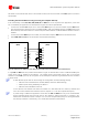

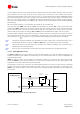


Table Of Contents
- Preface
- Contents
- 1 System description
- 1.1 Overview
- 1.2 Architecture
- 1.3 Pin-out
- 1.4 Operating modes
- 1.5 Power management
- 1.6 System functions
- 1.7 RF connection
- 1.8 SIM interface
- 1.9 Serial Communication
- 1.10 Audio
- 1.11 ADC input (LEON-G100 only)
- 1.12 General Purpose Input/Output (GPIO)
- 1.13 M2M Setup Schematic Example
- 1.14 Approvals
- 2 Design-In
- 3 Handling and soldering
- 4 Product Testing
- Appendix
- A Extra Features
- B Glossary
- Related documents
- Revision history
- Contact
LEON-G100/G200 - System Integration Manual
GSM.G1-HW-09002-F3 Preliminary System description
Page 52 of 101
Additional considerations
To avoid an increase in module power consumption, any external signal connected to the UART must be
set low or tri-stated when the module is in power-down mode. If the external signals in the application
circuit connected to the UART cannot be set low or tri-stated, a multi channel digital switch (e.g. Texas
Instruments SN74CB3Q16244) or a single channel analog switch (e.g. Texas Instruments TS5A3159 or
Texas Instruments TS5A63157) must be inserted between the two-circuit connections and set to high
impedance when the module is in power-down mode.
It is highly recommended to provide on an application board a direct access to RxD and TxD lines of the
module (in addition to access to these lines from an application processor). This enables a direct
connection of PC (or similar) to the module for execution of Firmware upgrade over the UART. Note that
the module FW upgrade over UART (using the RxD and TxD pins) starts at the module switch-on or
when the module is released from the reset state: it is suggested to provide access to the PWR_ON pin,
or to provide access to the RESET_N pin, or to provide access to the enabling of the DC supply
connected to the VCC pin, to start the module firmware upgrade over the UART.
1.9.1.5 MUX Protocol (3GPP 27.010)
The module has a software layer with MUX functionality complaint with 3GPP 27.010 [7].
This is a data link protocol (layer 2 of OSI model) using HDLC-like framing and operates between the module
(DCE) and the application processor (DTE). The protocol allows simultaneous sessions over the UART. Each
session consists of a stream of bytes transferring various kinds of data like SMS, CBS, GPRS, AT commands in
general. This permits, for example, SMS to be transferred to the DTE when a data connection is in progress.
The following channels are defined:
Channel 0: control channel
Channel 1 – 5: AT commands /data connection
Channel 6: GPS tunneling
For more details please refer to GSM Mux implementation Application Note [14].
1.9.2 DDC (I
2
C) interface
1.9.2.1 Overview
An I
2
C compatible Display Data Channel (DDC) interface for serial communication is implemented. This interface
is intended exclusively to access u-blox GPS receivers.
Name
Description
Remarks
SCL
I
2
C bus clock line
Fixed open drain. External pull-up required.
SDA
I
2
C bus data line
Fixed open drain. External pull-up required.
Table 18: DDC pins
DDC (I
2
C) interface pins ESD rating is 1 kV (contact discharge). A higher protection level could be
required if the lines are externally accessible on the application board. A higher protection level can be
achieved mounting an ESD protection (e.g. EPCOS CA05P4S14THSG varistor array) on the lines
connected to these pins if they are externally accessible on the application board.