
Integration Guide


Table Of Contents
- Preface
- Contents
- 1 System description
- 1.1 Overview
- 1.2 Architecture
- 1.3 Pin-out
- 1.4 Operating modes
- 1.5 Power management
- 1.6 System functions
- 1.7 RF connection
- 1.8 SIM interface
- 1.9 Serial Communication
- 1.10 Audio
- 1.11 ADC input (LEON-G100 only)
- 1.12 General Purpose Input/Output (GPIO)
- 1.13 M2M Setup Schematic Example
- 1.14 Approvals
- 2 Design-In
- 3 Handling and soldering
- 4 Product Testing
- Appendix
- A Extra Features
- B Glossary
- Related documents
- Revision history
- Contact
LEON-G100/G200 - System Integration Manual
GSM.G1-HW-09002-F3 Preliminary System description
Page 46 of 101
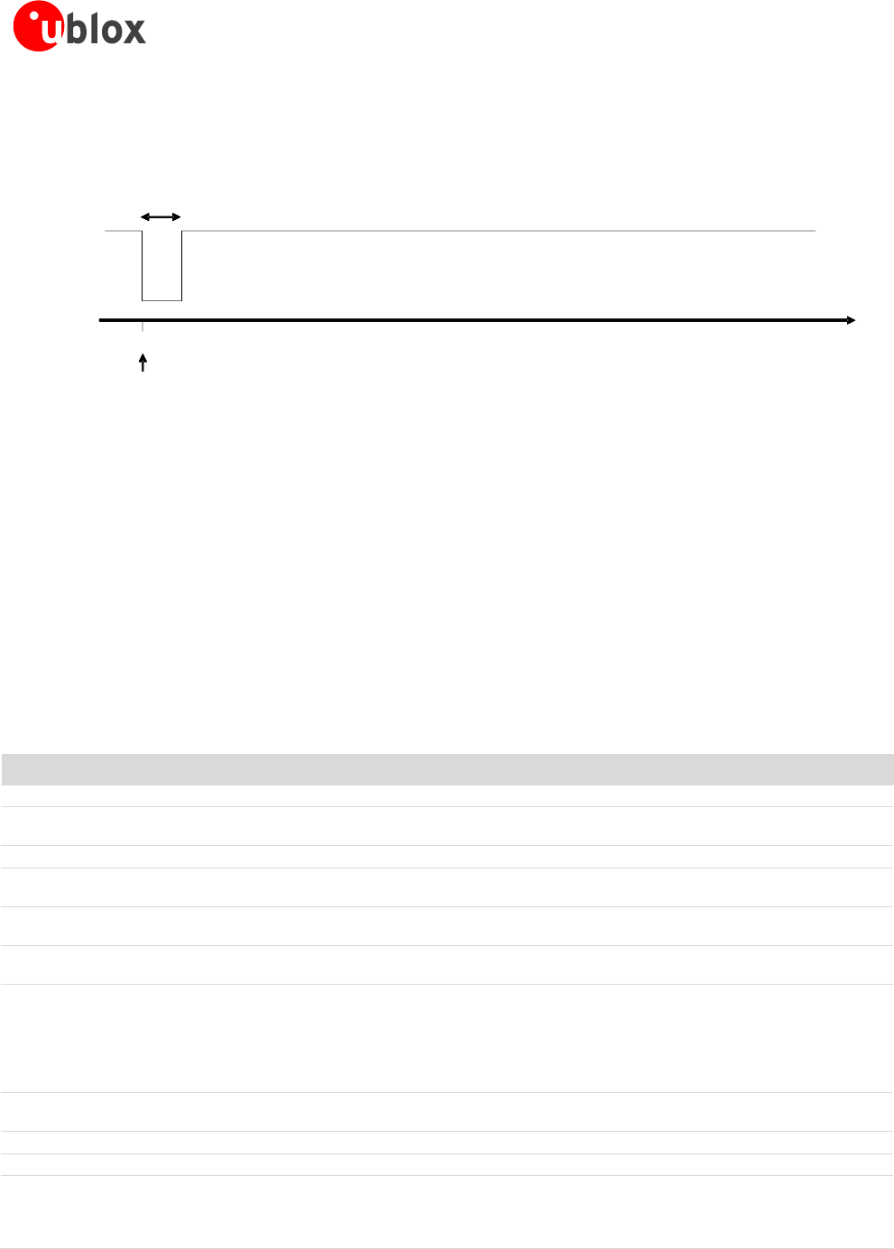
The RI line can notify an SMS arrival. When the SMS arrives, the RI line switches from OFF to ON for 1 s (see
Figure 27), if the feature is enabled by the proper AT command (please refer to u-blox 2G GSM/GPRS AT
Commands Manual [2], AT+CNMI command).
Figure 27: RI behavior at SMS arrival
1.9.1.3 UART and power-saving
The power saving configuration is controlled by the AT+UPSV command (for the complete description please
refer to u-blox 2G GSM/GPRS AT Commands Manual [2], AT+UPSV command). When power saving is enabled,
the module automatically enters idle-mode whenever possible, otherwise the active-mode is maintained by the
module. The AT+UPSV command sets the module power saving configuration, but also configures the UART
behavior in relation to the power saving configuration. The conditions for the module entering idle-mode also
depend on the UART power saving configuration.
The different power saving configurations that can be set by the AT+UPSV command are described in the
following subchapters and are summarized in Table 17. For more details on the command description please
refer to u-blox AT commands Manual [2].
AT+UPSV
HW flow control
RTS line
Communication during idle mode and wake up
0
Enabled (AT&K3)
ON
Data sent by the DTE will be correctly received by the module.
0
Enabled (AT&K3)
OFF
Data sent by the module will be buffered by the module and will be correctly received by
the DTE when it will be ready to receive data (i.e. RTS line will be ON).
0
Disabled (AT&K0)
ON
Data sent by the DTE will be correctly received by the module.
0
Disabled (AT&K0)
OFF
Data sent by the module will be correctly received by the DTE if it is ready to receive data,
otherwise data will be lost.
1
Enabled (AT&K3)
ON
Data sent by the DTE will be buffered by the DTE and will be correctly received by the
module when active-mode is entered.
1
Enabled (AT&K3)
OFF
Data sent by the module will be buffered by the module and will be correctly received by
the DTE when it is ready to receive data (i.e. RTS line will be ON).
1
Disabled (AT&K0)
ON
When a low-to-high transition occurs on the TxD input line, the module switches from
idle-mode to active-mode after 20 ms: this is the “wake up time” of the module. As a
consequence, the first character sent when the module is in idle-mode (i.e. the wake up
character) won’t be a valid communication character because it can’t be recognized, and
the recognition of the subsequent characters is guaranteed only after the complete wake-up
(i.e. after 20 ms).
1
Disabled (AT&K0)
OFF
Data sent by the module will be correctly received by the DTE if it is ready to receive data,
otherwise data will be lost.
2
Enabled (AT&K3)
ON
Not Applicable: HW flow control cannot be enabled with AT+UPSV=2.
2
Enabled (AT&K3)
OFF
Not Applicable: HW flow control cannot be enabled with AT+UPSV=2.
2
Disabled (AT&K0)
ON
The module is forced in active-mode and it doesn’t enter idle-mode until RTS line is set to
OFF state. When a high-to-low (i.e. OFF-to-ON) transition occurs on the RTS input line, the
module switches from idle-mode to active-mode after 20 ms: this is the “wake up time” of
the module.
SMS arrives
time [s]
0
RI ON
RI OFF
1s
SMS
time [s]
0
RI ON
RI OFF
1s