
Integration Guide


Table Of Contents
- Preface
- Contents
- 1 System description
- 1.1 Overview
- 1.2 Architecture
- 1.3 Pin-out
- 1.4 Operating modes
- 1.5 Power management
- 1.6 System functions
- 1.7 RF connection
- 1.8 SIM interface
- 1.9 Serial Communication
- 1.10 Audio
- 1.11 ADC input (LEON-G100 only)
- 1.12 General Purpose Input/Output (GPIO)
- 1.13 M2M Setup Schematic Example
- 1.14 Approvals
- 2 Design-In
- 3 Handling and soldering
- 4 Product Testing
- Appendix
- A Extra Features
- B Glossary
- Related documents
- Revision history
- Contact
LEON-G100/G200 - System Integration Manual
GSM.G1-HW-09002-F3 Preliminary System description
Page 45 of 101
If AT&S1 is set, the DSR module output line is set by default to OFF state (high level) at UART initialization. The
DSR line is then set to the OFF state when the module is in command mode and is set to the ON state when the
module is in data mode.
DTR signal behavior
The DTR module input line is set by default to OFF state (high level) at UART initialization. The DTR line is then
held by the module in the OFF state if the line is not activated by the DTE: an active pull-up is enabled inside the
module on the DTR input. Module behavior according to DTR status depends on the AT command
configuration (see u-blox 2G GSM/GPRS AT Commands Manual [2], &D AT command).
DCD signal behavior
If AT&C0 is set, the DCD module output line is set by default to ON state (low level) at UART initialization and is
then always held in the ON state.
If AT&C1 is set, the DCD module output line is set by default to OFF state (high level) at UART initialization. The
DCD line is then set by the module in accordance with the carrier detect status: ON if the carrier is detected, OFF
otherwise. In case of voice call DCD is set to ON state when the call is established. For a data call there are the
following scenarios:
GPRS data communication: Before activating the PPP protocol (data mode) a dial-up application must
provide the ATD*99***<context_number># to the module: with this command the module switches from
command mode to data mode and can accept PPP packets. The module sets the DCD line to the ON state,
then answers with a CONNECT to confirm the ATD*99 command. Please note that the DCD ON is not
related to the context activation but with the data mode
CSD data call: To establish a data call the DTE can send the ATD<number> command to the module which
sets an outgoing data call to a remote modem (or another data module). Data can be transparent (non
reliable) or non transparent (with the reliable RLP protocol). When the remote DCE accepts the data call, the
module DCD line is set to ON and the CONNECT <communication baudrate> string is returned by the
module. At this stage the DTE can send characters through the serial line to the data module which sends
them through the network to the remote DCE attached to a remote DTE
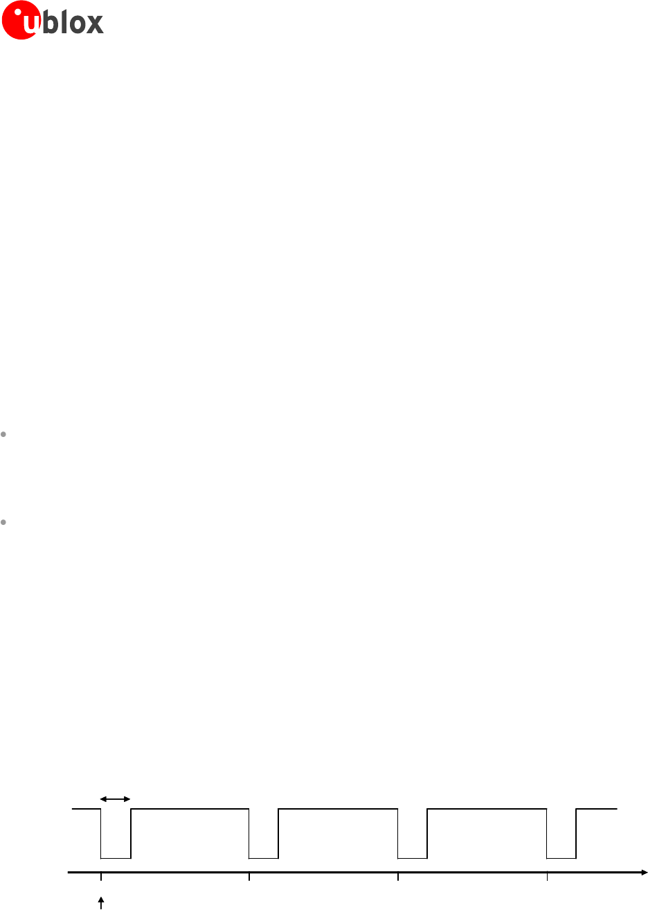
RI signal behavior
The RI module output line is set by default to the OFF state (high level) at UART initialization. Then, during an
incoming call, the RI line is switched from OFF state to ON state with a 4:1 duty cycle and a 5 s period (ON for
1 s, OFF for 4 s, see Figure 26), until the DTE attached to the module sends the ATA string and the module
accepts the incoming data call. The RING string sent by the module (DCE) to the serial port at constant time
intervals is not correlated with the switch of the RI line to the ON state.
Figure 26: RI behavior during an incoming call
1s
time [s]
151050
RI ON
RI OFF
Call incomes
1s
time [s]
151050
RI ON
RI OFF
Call incomes