
Integration Guide


Table Of Contents
- Preface
- Contents
- 1 System description
- 1.1 Overview
- 1.2 Architecture
- 1.3 Pin-out
- 1.4 Operating modes
- 1.5 Power management
- 1.6 System functions
- 1.7 RF connection
- 1.8 SIM interface
- 1.9 Serial Communication
- 1.10 Audio
- 1.11 ADC input (LEON-G100 only)
- 1.12 General Purpose Input/Output (GPIO)
- 1.13 M2M Setup Schematic Example
- 1.14 Approvals
- 2 Design-In
- 3 Handling and soldering
- 4 Product Testing
- Appendix
- A Extra Features
- B Glossary
- Related documents
- Revision history
- Contact
LEON-G100/G200 - System Integration Manual
GSM.G1-HW-09002-F3 Preliminary System description
Page 43 of 101
4800 b/s
9600 b/s
19200 b/s
38400 b/s
57600 b/s
115200 b/s (default value when autobauding is disabled)
The following baud-rates are available with autobauding only:
1200 b/s
230400 b/s
Automatic frame recognition is supported: this feature is enabled in conjunction with autobauding only, which is
enabled by default. The frame format can be:
8N1 (8 data bits, No parity, 1 stop bit)
8E1 (8 data bits, even parity, 1 stop bit)
8O1 (8 data bits, odd parity, 1 stop bit)
8N2 (8 data bits, No parity, 2 stop bits)
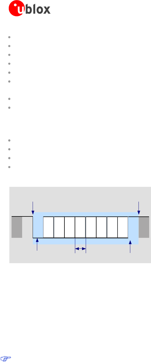
The default frame configuration with fixed baud rate is 8N1, described in the Figure 25.
D0 D1 D2 D3 D4 D5 D6 D7
Start of 1-Byte
transfer
Start Bit
(Always 0)
Possible Start of
next transfer
Stop Bit
(Always 1)
t
bit
= 1/(Baudrate)
Normal Transfer, 8N1
Figure 25: UART default frame format (8N1) description
1.9.1.2 UART signal behavior (AT commands interface case)
See Table 2 for a description of operating modes and states referred to in this section.
At the module switch-on, before the initialization of the UART interface (each pin is first tristated and then set to
its relative reset state reported in the pin description table in LEON-G100/G200 Data Sheet [1] (see the power on
sequence description in Figure 19). At the end of the boot sequence, the UART interface is initialized, the
module is by default in active mode and the UART interface is enabled. The configuration and the behavior of
the UART signals after the boot sequence are described below.
For a complete description of data and command mode please refer to u-blox 2G GSM/GPRS AT
Commands Manual [2].
RxD signal behavior
The module data output line (RxD) is set by default to OFF state (high level) at UART initialization. The module
holds RxD in OFF state until no data is transmitted by the module.