
Integration Guide


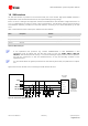
Table Of Contents
- Preface
- Contents
- 1 System description
- 1.1 Overview
- 1.2 Architecture
- 1.3 Pin-out
- 1.4 Operating modes
- 1.5 Power management
- 1.6 System functions
- 1.7 RF connection
- 1.8 SIM interface
- 1.9 Serial Communication
- 1.10 Audio
- 1.11 ADC input (LEON-G100 only)
- 1.12 General Purpose Input/Output (GPIO)
- 1.13 M2M Setup Schematic Example
- 1.14 Approvals
- 2 Design-In
- 3 Handling and soldering
- 4 Product Testing
- Appendix
- A Extra Features
- B Glossary
- Related documents
- Revision history
- Contact
LEON-G100/G200 - System Integration Manual
GSM.G1-HW-09002-F3 Preliminary System description
Page 40 of 101
1.8 SIM interface
An SIM card interface is provided on the board-to-board pins of the module. High-speed SIM/ME interface is
implemented as well as automatic detection of the required SIM supporting voltage.
Both 1.8 V and 3 V SIM types are supported: activation and deactivation with automatic voltage switch from 1.8
to 3 V is implemented, according to ISO-IEC 78-16-e specifications. The SIM driver supports the PPS (Protocol
and Parameter Selection) procedure for baud-rate selection, according to the values determined by the SIM
Card.
Table 14 describes the board-to-board pins related to the SIM interface:
Name
Description
Remarks
VSIM
SIM supply
1.80 V typical or 2.85 V typical automatically generated by the
module
SIM_CLK
SIM clock
3.25 MHz clock frequency
SIM_IO
SIM data
Internal 4.7 kΩ pull-up to VSIM
SIM_RST
SIM reset
Table 14: SIM Interface pins
A low capacitance ESD protection (e.g. Infineon ESD8V0L2B-03L or AVX USB0002RP or AVX
USB0002DP) must be placed near the SIM card holder on each line (VSIM, SIM_IO, SIM_CLK,
SIM_RST). SIM interface pins ESD rating is 1 kV (contact discharge): higher protection level is required if
the lines are connected to a SIM card holder/connector, so they are externally accessible on the
application board.
For more details about the general precautions for ESD immunity about SIM pins please refer to chapter
2.5.1.
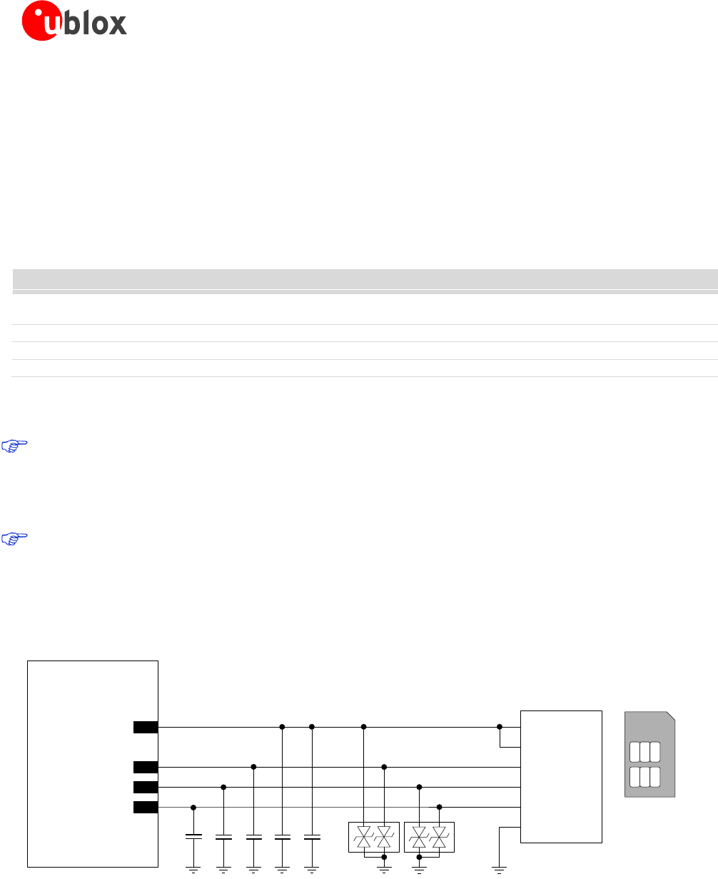
Figure 24 shows the minimal circuit connecting the LEON and the SIM card.
LEON-G100/G200
C1
SIM CARD
HOLDER
CCVCC (C1)
CCVPP (C6)
CCIO (C7)
CCCLK (C3)
CCRST (C2)
GND (C5)
C2 C3 C5
D1 D2
C
5
C
6
C
7
C
1
C
2
C
3
SIM Card
Bottom View
(contacts side)
J1
35
VSIM
33
SIM_IO
32
SIM_CLK
34
SIM_RST
C4
Figure 24: SIM interface application circuit