
Integration Guide


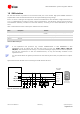
Table Of Contents
- Preface
- Contents
- 1 System description
- 1.1 Overview
- 1.2 Architecture
- 1.3 Pin-out
- 1.4 Operating modes
- 1.5 Power management
- 1.6 System functions
- 1.7 RF connection
- 1.8 SIM interface
- 1.9 Serial Communication
- 1.10 Audio
- 1.11 ADC input (LEON-G100 only)
- 1.12 General Purpose Input/Output (GPIO)
- 1.13 M2M Setup Schematic Example
- 1.14 Approvals
- 2 Design-In
- 3 Handling and soldering
- 4 Product Testing
- Appendix
- A Extra Features
- B Glossary
- Related documents
- Revision history
- Contact
LEON-G100/G200 - System Integration Manual
GSM.G1-HW-09002-F3 Preliminary System description
Page 38 of 101
OUT
IN
LEON-G100/G200
12.6 k
1.88 V
22
RESET_N
Application Processor
680 k
INPUT
OUT
IN
LEON-G100/G200
12.6 k
1.88 V
22
RESET_N
Application Processor
INPUT
22 k
330 k
OUT
IN
LEON-G100/G200
12.6 k
1.88 V
22
RESET_N
330 k
220
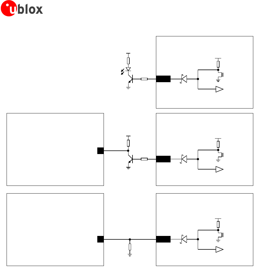
Figure 22: Application circuits to sense if the module is in the reset state
The RESET_N is set low by the module for 160 µs to indicate that an internal reset occurs.
The exact low level time interval depends on the implemented circuit, since the fall time of the RESET_N low
pulse depends on the pull-down value, which must be greater or equal to 680 kΩ.
For example, if LEON RESET_N pin is connected through a 680 kΩ pull-down resistor to an input pin of an
application processor in the 1.8 V domain (i.e. Vih = 0.7 x 1.8 V = 1.26 V, Vil = 0.3 x 1.8 V = 0.54 V), the low
level time interval will be ~145 µs, since the 680 kΩ pull-down forces a ~35 µs 100%-0% fall time, as illustrated
in the Figure 23.