
Integration Guide


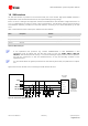
Table Of Contents
- Preface
- Contents
- 1 System description
- 1.1 Overview
- 1.2 Architecture
- 1.3 Pin-out
- 1.4 Operating modes
- 1.5 Power management
- 1.6 System functions
- 1.7 RF connection
- 1.8 SIM interface
- 1.9 Serial Communication
- 1.10 Audio
- 1.11 ADC input (LEON-G100 only)
- 1.12 General Purpose Input/Output (GPIO)
- 1.13 M2M Setup Schematic Example
- 1.14 Approvals
- 2 Design-In
- 3 Handling and soldering
- 4 Product Testing
- Appendix
- A Extra Features
- B Glossary
- Related documents
- Revision history
- Contact
LEON-G100/G200 - System Integration Manual
GSM.G1-HW-09002-F3 Preliminary System description
Page 37 of 101
Reset
push button
OUT
IN
LEON-G100/G200
12.6 k
1.88 V
22
RESET_N
OUT
IN
LEON-G100/G200
12.6 k
1.88 V
22
RESET_N
Application Processor
ESD
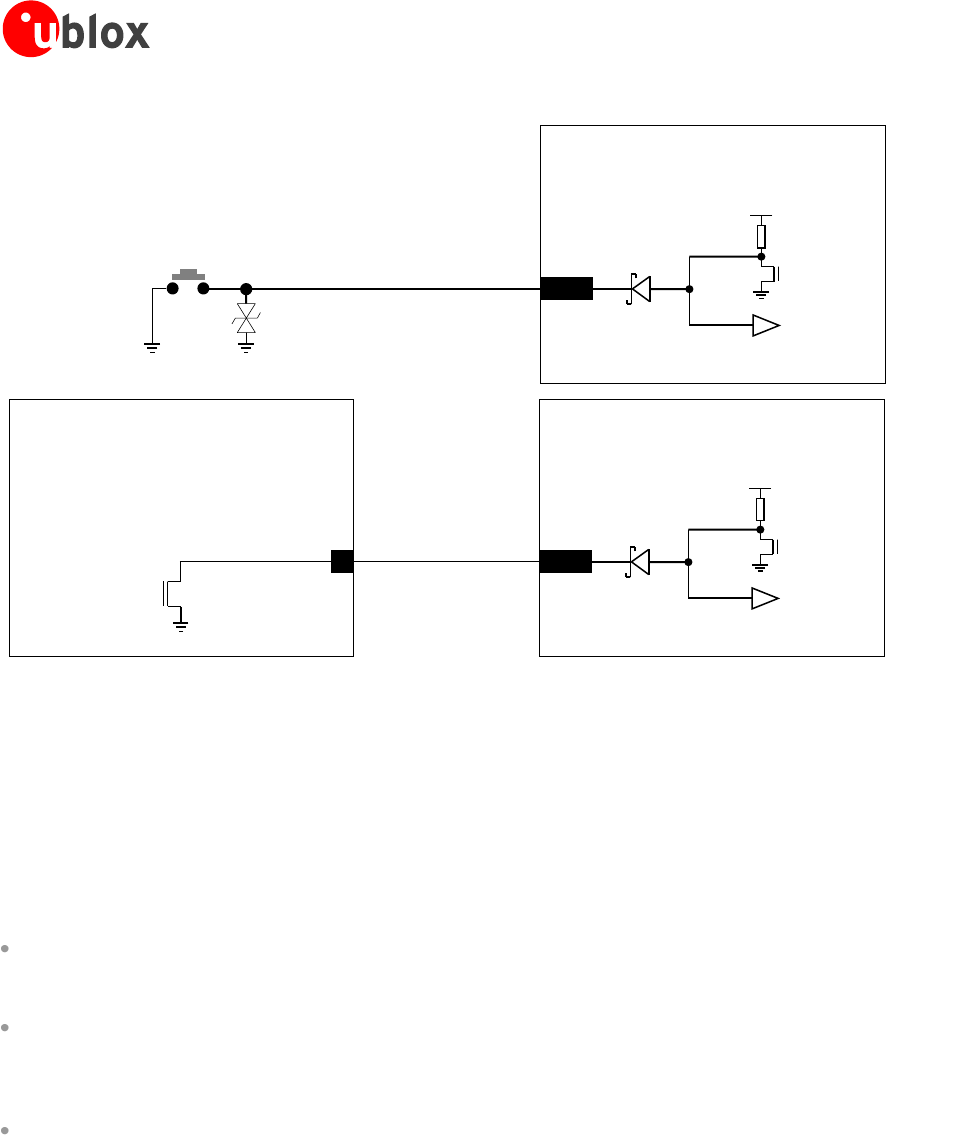
Figure 21: Application circuits to reset the module using a push button or using an application processor
When the module is in power-off mode or an internal reset occurs, RESET_N is pulled low by the module itself:
RESET_N acts as an output pin in these cases since an internal open drain FET (illustrated in Figure 21 and in
Figure 22) pulls the line low.
The RESET_N pin can indicate to an external application that the module is switched on and is not in the reset
state: RESET_N is high in these cases and is low otherwise. To sense the RESET_N level (i.e. both the high level
and the low level), the external circuit has to be able to cause a small current through the series Schottky diode
integrated in the module as protection (illustrated in Figure 21 and Figure 22) by means of a very weak pull-
down. One of the following application circuits can be implemented to determine the RESET_N status:
RESET_N connected to an LED that emits light when the module is powered up and not in reset state and
doesn’t emit light otherwise, through a biased inverting NPN transistor, with a series base resistor with a
resistance value greater or equal to 330 kΩ
RESET_N connected to an input pin of an application processor that senses a low logic level (0 V) when the
module is powered up and is not in reset state and senses a high logic level (i.e. 3.0 V) otherwise, through
an inverting and level shifting NPN transistor, with a series base resistor with a resistance value greater or
equal to 330 kΩ
RESET_N connected to an input pin of the application processor that senses a high logic level (1.8 V) when
the module is powered up and is not in reset state and senses a low logic level (0 V) otherwise, through a
weak pull-down resistor, with a resistance value greater or equal to 680 kΩ.
Examples of application circuits to sense the RESET_N level are shown in the Figure 22.