
Integration Guide


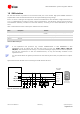
Table Of Contents
- Preface
- Contents
- 1 System description
- 1.1 Overview
- 1.2 Architecture
- 1.3 Pin-out
- 1.4 Operating modes
- 1.5 Power management
- 1.6 System functions
- 1.7 RF connection
- 1.8 SIM interface
- 1.9 Serial Communication
- 1.10 Audio
- 1.11 ADC input (LEON-G100 only)
- 1.12 General Purpose Input/Output (GPIO)
- 1.13 M2M Setup Schematic Example
- 1.14 Approvals
- 2 Design-In
- 3 Handling and soldering
- 4 Product Testing
- Appendix
- A Extra Features
- B Glossary
- Related documents
- Revision history
- Contact

LEON-G100/G200 - System Integration Manual
GSM.G1-HW-09002-F3 Preliminary System description
Page 36 of 101
1.6.3 Module reset
LEON-G100/G200 modules can be reset using the RESET_N pin: when the RESET_N pin is forced low for at
least 50 ms, an “external” or “hardware” reset is performed, that causes an asynchronous reset of the entire
module, except for the RTC. Forcing an “external” or “hardware” reset, the current parameter settings are not
saved in the module’s non-volatile memory and a proper network detach is not performed.
LEON-G100/G200 modules can also be reset by means of the AT command AT+CFUN (more details in u-blox 2G
GSM/GPRS AT Commands Manual [2]): in this case an “internal” or “software” reset is performed, that causes,
like the “external” or “hardware” reset, an asynchronous reset of the entire module except for the RTC. Forcing
an “internal” or “software” reset, the current parameter settings are saved in the module’s non-volatile memory
and a proper network detach is performed.
The RESET_N pin is pulled low by the module when the module is in power-off mode or an internal reset
occurs. In these cases an internal open drain FET pulls the line low.
Name
Description
Remarks
RESET_N
Reset signal
A series Schottky diode is integrated in the module as protection.
An internal 12.6 kΩ pull-up resistor pulls the line to 1.88 V when
the module is not in the reset state. An internal open drain FET
pulls the line low when an internal reset occurs and when the
module is in power down mode.
Table 12: Reset pin
RESET_N pin ESD rating is 1 kV (contact discharge). A higher protection level could be required if the
line is externally accessible on the application board. A higher protection level can be achieved mounting
an ESD protection (e.g. EPCOS CA05P4S14THSG varistor array) on the line connected to this pin if it is
externally accessible on the application board.
For more details about the general precautions for ESD immunity about RESET_N pin please refer to
chapter 2.5.1.
The electrical characteristics of RESET_N are different from the other digital I/O interfaces. The high and low
logic levels have different operating ranges and absolute maximum ratings. The detailed electrical characteristics
are described in the LEON-G100/G200 Data Sheet [1].
As described in the Figure 21, a series Schottky diode is mounted inside the module on the RESET_N pin to
increase the maximum allowed input voltage up to 4.5 V as operating range. Nevertheless the module senses a
low level when the RESET_N pin is forced low from the external.
As described in Figure 21, the module has an internal pull-up resistor (12.6 kΩ typical) which pulls the level on
the RESET_N pin to 1.88 V (typical) when the module is not in reset state. Therefore an external pull-up is not
required on the application board.
Forcing RESET_N low for at least 50 ms will cause an external reset of the module. When RESET_N is released
from the low level, the module automatically starts its power-on reset sequence.
If RESET_N is connected to an external device (e.g. an application processor on an application board) an open
drain output can be directly connected without any external pull-up. Otherwise, use a push-pull output. Make
sure to fix the proper level on RESET_N in all possible scenarios, to avoid unwanted reset of the module.
The reset state of each digital pin is reported in the pin description table in the LEON-G100/G200 Data Sheet [1].