
Integration Guide


Table Of Contents
- Preface
- Contents
- 1 System description
- 1.1 Overview
- 1.2 Architecture
- 1.3 Pin-out
- 1.4 Operating modes
- 1.5 Power management
- 1.6 System functions
- 1.7 RF connection
- 1.8 SIM interface
- 1.9 Serial Communication
- 1.10 Audio
- 1.11 ADC input (LEON-G100 only)
- 1.12 General Purpose Input/Output (GPIO)
- 1.13 M2M Setup Schematic Example
- 1.14 Approvals
- 2 Design-In
- 3 Handling and soldering
- 4 Product Testing
- Appendix
- A Extra Features
- B Glossary
- Related documents
- Revision history
- Contact
LEON-G100/G200 - System Integration Manual
GSM.G1-HW-09002-F3 Preliminary System description
Page 35 of 101
1.6.2 Module power off
The correct way to switch off LEON-G100/G200 modules is by means of the AT command AT+CPWROFF (more
details in u-blox 2G GSM/GPRS AT Commands Manual [2]): in this way the current parameter settings are saved
in the module’s non-volatile memory and a proper network detach is performed.
An under-voltage shutdown will be done if VCC falls below the extended operating range minimum limit (see
LEON-G100/G200 Data Sheet [1]), but in this case the current parameter settings are not saved in the module’s
non-volatile memory and a proper network detach cannot be performed.
When the AT+CPWROFF command is sent, the module starts the switch-off routine replying OK on the AT
interface: during this phase, the current parameter settings are saved in the module’s non-volatile memory, a
network detach is performed and all module interfaces are disabled (i.e. the digital pins are locked in tri-state by
the module). Since the time to perform a network detach depends on the network settings, the duration of this
phase can differ from the typical value reported in Figure 20. At the end of the switch-off routine, the module
pulls the RESET_N pin low to indicate that it is in power-off mode: all the digital pins are locked in tri-state by
the module and all the internal LDO voltage regulators except the RTC supply (V_BCKP) are turned off in a
defined power-off sequence. The module remains in power-off mode as long as a switch-on event doesn’t occur
(i.e. a low level on the PWR_ON pin, or an RTC alarm, or a charger detection), and enters not-powered mode if
the supply is removed from the VCC pin.
To avoid an increase of module current consumption in power-down mode, any external signal
connected to the module digital pins (UART interface, Digital audio interface, HS_DET, GPIOs) must be
set low or tri-stated when the module is in the not-powered or power-off modes. If the external signals
connected to the module digital pins cannot be set low or tri-stated, insert a switch (e.g. Texas
Instruments SN74CB3Q16244, or Texas Instruments TS5A3159, or Texas Instruments TS5A63157)
between the two-circuit connections. Set the switch to high impedance when the module is in power-
down mode (to avoid an increase of the module power consumption).
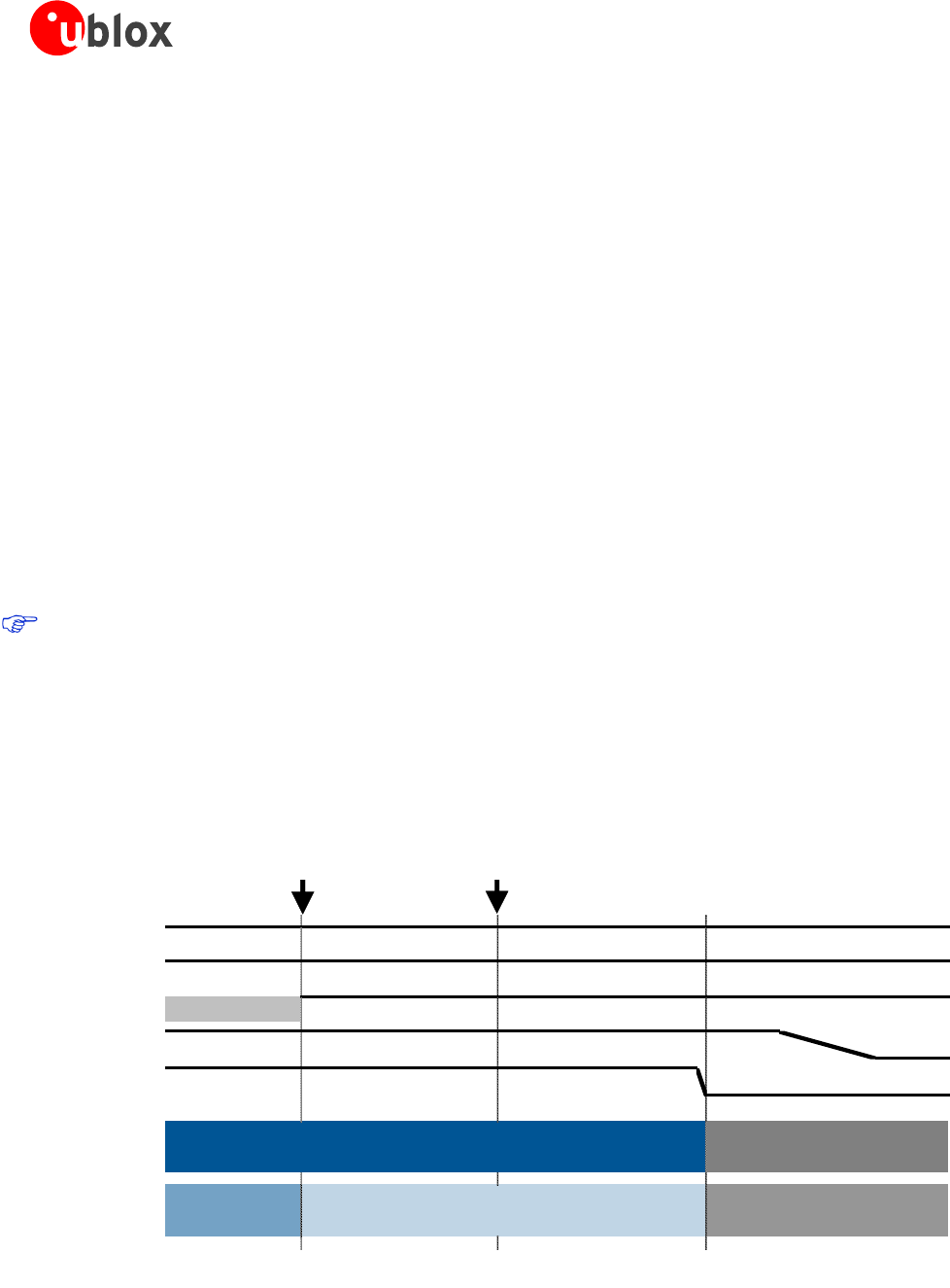
The power-off sequence is described in Figure 20.
VCC
V_BCKP
PWR_ON *
LDOs
RESET_N
System State
BB Pads State Operational
OFF
Tristate / Floating
ON
Operational → Tristate / Floating
AT+CPWROFF
sent to the module
0 ms
~50 ms
~400 ms
OK
replied by the module
Figure 20: Power off sequence description (* - the PWR_ON signal state is not relevant during this phase)