
Integration Guide


Table Of Contents
- Preface
- Contents
- 1 System description
- 1.1 Overview
- 1.2 Architecture
- 1.3 Pin-out
- 1.4 Operating modes
- 1.5 Power management
- 1.6 System functions
- 1.7 RF connection
- 1.8 SIM interface
- 1.9 Serial Communication
- 1.10 Audio
- 1.11 ADC input (LEON-G100 only)
- 1.12 General Purpose Input/Output (GPIO)
- 1.13 M2M Setup Schematic Example
- 1.14 Approvals
- 2 Design-In
- 3 Handling and soldering
- 4 Product Testing
- Appendix
- A Extra Features
- B Glossary
- Related documents
- Revision history
- Contact
LEON-G100/G200 - System Integration Manual
GSM.G1-HW-09002-F3 Preliminary System description
Page 34 of 101
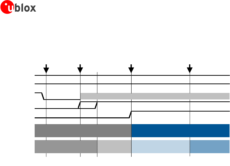
high by the action of the internal pull-up and the configuration of the module interfaces will start: during this
phase any digital pin is set in a proper sequence from reset state to the default operational configuration. The
module is fully ready to operate when all the interfaces are configured.
VCC
V_BCKP
PWR_ON
LDOs
RESET_N
System State
BB Pads State
Reset → Operational Operational
Tristate / Floating
Reset
OFF
ON
*
Start-up
event
0 ms
~22 ms
~23 ms
~45 ms
~1500 ms
PWR_ON
can be set high
Start of interfaces'
configuration
All interfaces
are configured
Figure 19: Power on sequence description (* - the PWR_ON signal state is not relevant during this phase)