
Integration Guide


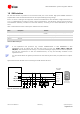
Table Of Contents
- Preface
- Contents
- 1 System description
- 1.1 Overview
- 1.2 Architecture
- 1.3 Pin-out
- 1.4 Operating modes
- 1.5 Power management
- 1.6 System functions
- 1.7 RF connection
- 1.8 SIM interface
- 1.9 Serial Communication
- 1.10 Audio
- 1.11 ADC input (LEON-G100 only)
- 1.12 General Purpose Input/Output (GPIO)
- 1.13 M2M Setup Schematic Example
- 1.14 Approvals
- 2 Design-In
- 3 Handling and soldering
- 4 Product Testing
- Appendix
- A Extra Features
- B Glossary
- Related documents
- Revision history
- Contact

LEON-G100/G200 - System Integration Manual
GSM.G1-HW-09002-F3 Preliminary System description
Page 32 of 101
1.6.1.1 Rising edge on VCC
When a supply is connected to VCC pin, the module supply supervision circuit controls the subsequent activation
of the power up state machines: the module is switched-on when the voltage rises up to the VCC normal
operating range minimum limit (3.35 V) starting from a voltage value lower than 2.25 V.
1.6.1.2 Low level on the PWR_ON
Power-on sequence of the module starts when a low level is forced on the PWR_ON signal for at least 5 ms.
The electrical characteristics of the PWR_ON input pin are different from the other digital I/O interfaces: the high
and the low logic levels have different operating ranges and the pin is tolerant against voltages up to the battery
voltage. The detailed electrical characteristics are described in LEON-G100/G200 Data Sheet [1].
PWR_ON pin has high input impedance and is weakly pulled to the high level on the module. Avoid
keep it floating in noisy environment. To hold the high logic level stable, the PWR_ON pin must be
connected to a pull-up resistor (e.g. 100 kΩ) biased by a supply rail present on the application board, in
range from 1.8 V to 4.5 V, which supply rail should be available when the module is in power-off mode.
If PWR_ON input is connected to a push button that shorts the PWR_ON pin to ground, the V_BCKP supply
pin or the VCC supply pin of the module can be used to bias the pull-up resistor.
If PWR_ON input is connected to an external device (e.g. application processor), it is suggested to use an open
drain output of the external device with an external pull-up. Connect the pull-up the V_BCKP supply pin or the
VCC supply pin of the module, or to another supply rail present on the application board, in range from 1.8 V to
4.5 V, which supply rail should be available when the module is in power-off mode.
If PWR_ON pin is connected to a push-pull output pin of an application processor, the pull-up can be provided
to pull high the PWR_ON level when the application processor is switched off. If the high-level voltage of the
push-pull output pin of the application processor is greater than 2.0 V, the V_BCKP supply cannot be used to
bias the pull-up resistor: the supply rail of the application processor or the VCC supply can be used. Using a
push-pull output of the external device, take care to fix the proper level in all the possible scenarios to avoid an
inappropriate switch-on of the module.
The module can be switched-on by forcing a low level for at least 5 ms on the PWR_ON pin: the
module is not switched-on by a falling edge provided on the PWR_ON pin. The suggested PWR_ON
pull-up resistor value is 100 kΩ: lower resistance value will increase the module power-off consumption.