
Integration Guide


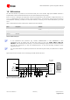
Table Of Contents
- Preface
- Contents
- 1 System description
- 1.1 Overview
- 1.2 Architecture
- 1.3 Pin-out
- 1.4 Operating modes
- 1.5 Power management
- 1.6 System functions
- 1.7 RF connection
- 1.8 SIM interface
- 1.9 Serial Communication
- 1.10 Audio
- 1.11 ADC input (LEON-G100 only)
- 1.12 General Purpose Input/Output (GPIO)
- 1.13 M2M Setup Schematic Example
- 1.14 Approvals
- 2 Design-In
- 3 Handling and soldering
- 4 Product Testing
- Appendix
- A Extra Features
- B Glossary
- Related documents
- Revision history
- Contact
LEON-G100/G200 - System Integration Manual
GSM.G1-HW-09002-F3 Preliminary System description
Page 31 of 101
LEON-G100/G200
C1
(a)
2
V_BCKP
R2
C2
(superCap)
(b)
2
V_BCKP
2V
(c)
2
V_BCKP
LEON-G100/G200 LEON-G100/G200
Figure 17: Real time clock supply (V_BCKP) application circuits: (a) using a 100 µF capacitor to let the RTC run for 50 seconds at
25°C; (b) using a 70 mF capacitor to let the RTC run for ~10 hours at 25°C when the VCC supply is removed; (c) using a not
rechargeable battery
Reference
Description
Part Number - Manufacturer
C1
100 µF Tantalum Capacitor
GRM43SR60J107M - Murata
R2
4.7 kΩ Resistor 0402 5% 0.1 W
RC0402JR-074K7L - Yageo Phycomp
C2
70 mF Capacitor
XH414H-IV01E - Seiko Instruments
Table 10: Example of components for V_BCKP buffering
If longer buffering time is required to allow the time reference to run during a disconnection of the VCC supply,
a rechargeable battery, which has to be able to provide a 2.0 V nominal voltage and must not exceed the
maximum operating voltage value of 2.25 V, can be connected to the V_BCKP pin with a proper series resistor.
Otherwise a not rechargeable battery, which has to be able to provide a 2.0 V nominal voltage and must not
exceed the maximum operating voltage value of 2.25 V, can be connected to the V_BCKP pin with a proper
series resistor and a proper series diode. The purpose of the series resistor is to limit the battery charging current
due to the battery specifications, and also to let a fast rise time of the voltage value at the V_BCKP pin after
VCC supply has been provided. The purpose of the series diode is to avoid a current flow from the V_BCKP pin
of the module to the not rechargeable battery.
1.6 System functions
1.6.1 Module power on
The power-on sequence of the module is initiated in one of 4 ways:
Rising edge on the VCC pin to a valid voltage as module supply
Low level on the PWR_ON signal
RTC alarm
Charger detection on the V_CHARGE and CHARGE_SENSE pins (LEON-G200 only)
Name
Description
Remarks
PWR_ON
Power-on input
PWR_ON pin has high input impedance.
Do not keep floating in noisy environment: external pull-up
required.
Table 11: Power-on pin
PWR_ON pin ESD rating is 1 kV (contact discharge). A higher protection level could be required if the
line is externally accessible on the application board. A higher protection level can be achieved mounting
an ESD protection (e.g. EPCOS CA05P4S14THSG varistor array) on the line connected to this pin if it is
externally accessible on the application board.