
Integration Guide


Table Of Contents
- Preface
- Contents
- 1 System description
- 1.1 Overview
- 1.2 Architecture
- 1.3 Pin-out
- 1.4 Operating modes
- 1.5 Power management
- 1.6 System functions
- 1.7 RF connection
- 1.8 SIM interface
- 1.9 Serial Communication
- 1.10 Audio
- 1.11 ADC input (LEON-G100 only)
- 1.12 General Purpose Input/Output (GPIO)
- 1.13 M2M Setup Schematic Example
- 1.14 Approvals
- 2 Design-In
- 3 Handling and soldering
- 4 Product Testing
- Appendix
- A Extra Features
- B Glossary
- Related documents
- Revision history
- Contact
LEON-G100/G200 - System Integration Manual
GSM.G1-HW-09002-F3 Preliminary System description
Page 26 of 101
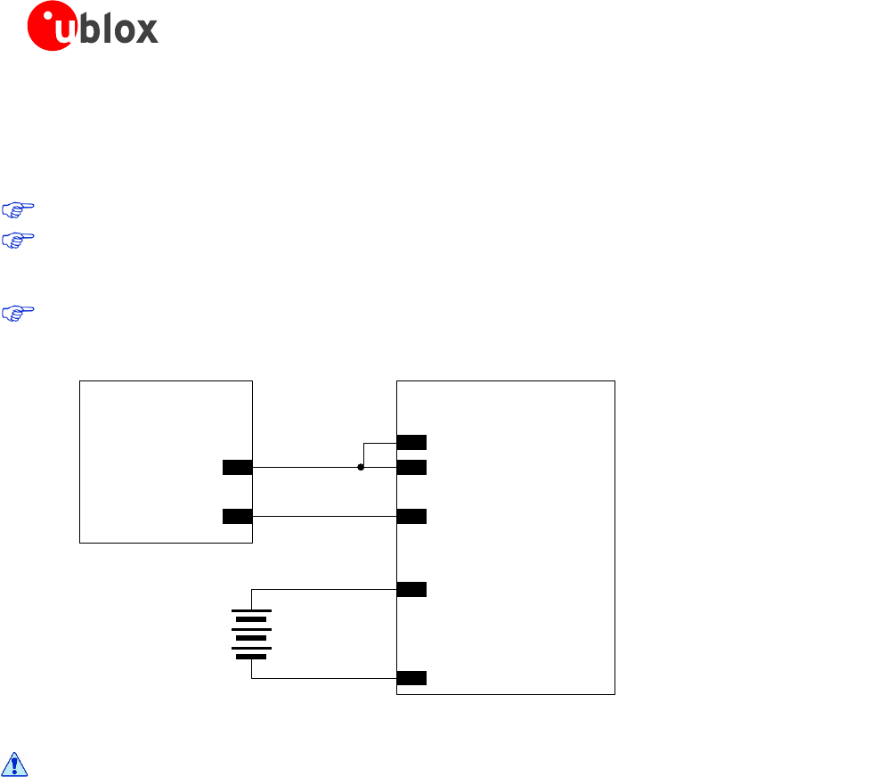
The V_CHARGE pin is the charger supply input: it sinks the charge current that is typically in the order of several
hundred of mA. The CHARGE_SENSE pin is connected to an internal ADC converter to measure the charging
voltage: it senses the charger voltage and sinks a few µA.
V_CHARGE and CHARGE_SENSE pins must be externally connected together as shown in Figure 14.
There may not be any capacitor on the charge path: a straight connection must be provided between
the output of the external supply used as charging source and V_CHARGE and CHARGE_SENSE pins of
the module.
If the battery charging process is not managed by the GSM module, V_CHARGE and CHARGE_SENSE
pins can be left floating on the application board.
LEON-G200
+
Charger
Voltage and
current limited
Li-Ion
Battery
5
CHARGE_SENSE
4
V_CHARGE
GND
50
VCC
GND
-
+
-
Figure 14: Connection of an external DC supply used as charger and a Li-Ion battery to the LEON-G200 module
To prevent damage to the module and the battery, use only chargers that comply with the
characteristics given in section 1.5.4.2.
1.5.4.1 Charging process description
A valid charger is recognized if the voltage provided to V_CHARGE and CHARGE_SENSE pins are within the
operating range limits (5.6 V minimum, 15 V maximum). If the module is switched off, the charger circuitry
generates the power on in charging mode after charger detection.
The algorithm that controls battery charging, implements a classic Li-Ion battery charging process, divided into 4
phases:
1. Pre-Charge, at low current, for deeply discharged batteries (VCC voltage within 0 V and 3.1 V typical)
2. Fast Charge, at the maximum current provided by the external DC supply used as charger that must be
current limited, for discharged batteries (VCC voltage within 3.1 V typical and 4.2 V typical)
3. Top Charge, to complete the over-charging of the batteries, after the maximum voltage is reached (VCC
voltage equal to 4.2 V typical)
4. Trickle Charge, to maintain the battery at higher level of charge, if the external DC supply used as charger
remains connected
If the batteries are deeply discharged (VCC voltage within 0 V and 3.1 V typical with 7% tolerance due to
change in temperature and life time), and the device is in not-powered mode, the charger circuit starts
pre-charging when a valid voltage is provided to V_CHARGE and CHARGE_SENSE pins of the module. In the
pre-charging phase, the charge transistor switch mounted inside the module is pulsed with a 100 Hz clock and