
Integration Guide


Table Of Contents
- Preface
- Contents
- 1 System description
- 1.1 Overview
- 1.2 Architecture
- 1.3 Pin-out
- 1.4 Operating modes
- 1.5 Power management
- 1.6 System functions
- 1.7 RF connection
- 1.8 SIM interface
- 1.9 Serial Communication
- 1.10 Audio
- 1.11 ADC input (LEON-G100 only)
- 1.12 General Purpose Input/Output (GPIO)
- 1.13 M2M Setup Schematic Example
- 1.14 Approvals
- 2 Design-In
- 3 Handling and soldering
- 4 Product Testing
- Appendix
- A Extra Features
- B Glossary
- Related documents
- Revision history
- Contact
LEON-G100/G200 - System Integration Manual
GSM.G1-HW-09002-F3 Preliminary System description
Page 25 of 101
ACTIVE MODE
20-22 mA 20-22 mA
~150 mA
RX+DSP
Enabled
20-22 mA
~150 mA
0.47-2.12 s
Paging period
Time [s]
Current [mA]
150
100
50
0
Time [ms]
Current [mA]
150
100
50
0
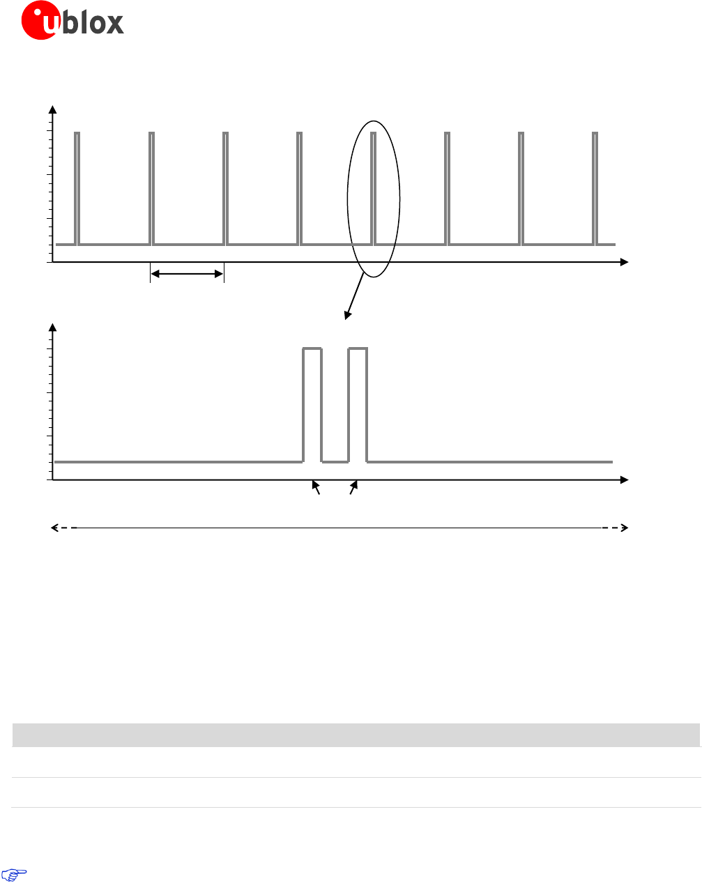
Figure 13: Description of the VCC current consumption profile versus time when power saving is disabled: active-mode is
always held, and the receiver and the DSP are periodically activated to monitor the paging channel for paging block reception
1.5.4 Battery charger (LEON-G200 only)
For battery charging functionalities the module is provided with integrated circuitry and software. Two pins are
available to connect the positive pole of the external DC supply used as charger.
Name
Description
Remarks
V_CHARGE
Charger Voltage Supply Input
V_CHARGE and CHARGE_SENSE pins must be externally
connected together.
CHARGE_SENSE
Charger Voltage Measurement Input
V_CHARGE and CHARGE_SENSE pins must be externally
connected together.
Table 8: Battery charger pins
V_CHARGE and CHARGE_SENSE pins ESD rating is 1 kV (contact discharge). A higher protection level
could be required if the lines are externally accessible on the application board. A higher protection level
can be achieved mounting an ESD protection (e.g. EPCOS CA05P4S14THSG varistor array) on the lines
connected to these pins if they are externally accessible on the application board.