
Integration Guide


Table Of Contents
- Preface
- Contents
- 1 System description
- 1.1 Overview
- 1.2 Architecture
- 1.3 Pin-out
- 1.4 Operating modes
- 1.5 Power management
- 1.6 System functions
- 1.7 RF connection
- 1.8 SIM interface
- 1.9 Serial Communication
- 1.10 Audio
- 1.11 ADC input (LEON-G100 only)
- 1.12 General Purpose Input/Output (GPIO)
- 1.13 M2M Setup Schematic Example
- 1.14 Approvals
- 2 Design-In
- 3 Handling and soldering
- 4 Product Testing
- Appendix
- A Extra Features
- B Glossary
- Related documents
- Revision history
- Contact
LEON-G100/G200 - System Integration Manual
GSM.G1-HW-09002-F3 Preliminary System description
Page 20 of 101
5 V
C1 R1
IN OUT
ADJ
GND
1
2
4
5
3
C2R2
R3
U1
SHDN
LEON-G100
LEON-G200
50
VCC
GND
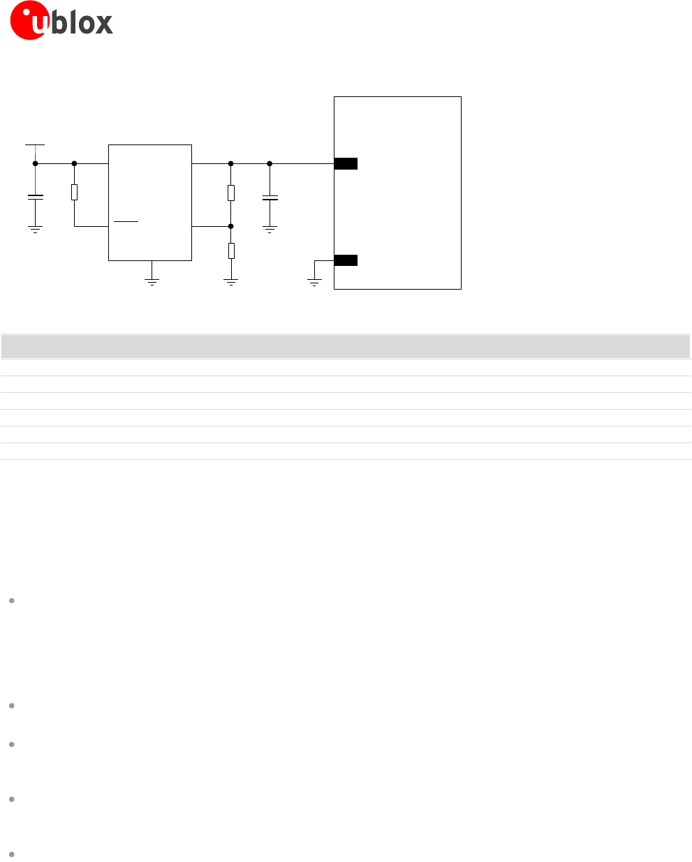
Figure 8: Suggested schematic design for the VCC voltage supply application circuit using an LDO linear regulator
Reference
Description
Part Number - Manufacturer
C1
10 µF Capacitor Ceramic X5R 0603 20% 6.3 V
GRM188R60J106ME47 - Murata
C2
10 µF Capacitor Ceramic X5R 0603 20% 6.3 V
GRM188R60J106ME47 - Murata
R1
47 kΩ Resistor 0402 5% 0.1 W
RC0402JR-0747KL - Yageo Phycomp
R2
4.7 kΩ Resistor 0402 5% 0.1 W
RC0402JR-074K7L - Yageo Phycomp
R3
2.2 kΩ Resistor 0402 5% 0.1 W
RC0402JR-072K2L - Yageo Phycomp
U1
LDO Linear Regulator ADJ 3.0 A
LT1764AEQ#PBF - Linear Technology
Table 6: Suggested components for VCC voltage supply application circuit using an LDO linear regulator
Rechargeable Li-Ion battery
The characteristics of the rechargeable Li-Ion battery connected to VCC pin should meet the following
requirements:
Maximum pulse and DC discharge current: the rechargeable Li-Ion battery with its output circuit has to
be capable to deliver 2.5 A current pulses with 1/8 duty cycle to VCC pin and has to be capable to deliver a
DC current greater than the module maximum average current consumption to VCC pin. Note that the
maximum pulse discharge current and the maximum DC discharge current are not always reported in
batteries data sheet, but the maximum DC discharge current is typically almost equal to the battery capacity
in Ampere-hours divided by 1 hour
DC series resistance: the rechargeable Li-Ion battery with its output circuit has to be capable to avoid a
VCC voltage drop greater than 400 mV during transmit bursts
Maximum charging voltage (overcharge detection voltage): if the charging process is managed by the
GSM module, the overcharge detection voltage of the used battery pack, which enables battery protection,
must be greater or equal than 4.3 V, to be charged by the GSM module
Charging operating temperature range: if the charging process is managed by the GSM module, the
charging operating temperature range of the used battery pack must include the 0°C-40°C range, to be
charged by the GSM module
Maximum DC charging current: the rechargeable Li-Ion battery has to be capable to be charged by the
charging current provided by the selected external charger. Note that the maximum DC charging current is
not always reported in batteries data sheet, but the maximum DC charging current is typically almost equal
to the battery capacity in Ampere-hours divided by 1 hour
Primary (disposable) battery
The characteristics of the primary (non-rechargeable) battery connected to VCC pin should meet the following
requirements: